Electronic visual headset with vision correction

a technology of eye glasses and eye glasses, applied in the field of optics, can solve the problems of unclear tracking methods, cumbersome calibration process, and blurry display for most naked eye users, and achieve the effects of reducing the number of eye glasses, and reducing the number of eyeglasses

Inactive Publication Date: 2021-02-11
ZAVOYSKIKH ANTON
View PDF7 Cites 3 Cited by
  • Summary
  • Abstract
  • Description
  • Claims
  • Application Information

AI Technical Summary

Benefits of technology

[0029]Variable-magnification lenses are situated between the user's eyes and the display. These lenses present virtual images of the display at the intended focal plane, thus avoiding vergence-accommodation conflict.
[0031]The processor can manipulate the displayed image in a variety of ways. It can magnify the scene. It can minify the scene, which allows for greater peripheral vision. It can enhance brightness for night vision. It can enhance color to correct color blindness. It can alter wavelengths of light to enable infra-red or ultra-violet vision.
[0032]The exterior of the eyeglass lenses may also be a high-resolution (e.g. DLP or OLED) display. Internal cameras take real-time images of the user's eyes, which are presented on the exterior displays. This creates the illusion to nearby people that they are seeing right through the glasses to the user's eyes.

Problems solved by technology

Most AR / VR devices assume that the wearer has perfect eyes, leading to blurry displays for most naked-eye users.
The best solution discussed so far is a cumbersome calibration process.
This tracking method has clear limitations.
It is inconvenient and expensive for a user to get an optometric exam before using the device.
If a headset is calibrated to one user, then it is not easily interchangeable to other users unless they also have their prescriptions available.
When the eyes are forced into an artificial state of changing vergence but fixed accommodation, the brain gets confused.
This can lead to poor imaging, disorientation, eye fatigue, headaches, or vertigo.
AR / VR glasses have the potential to greatly obstruct the eyes.

Method used


Image

  • Electronic visual headset with vision correction
  • Electronic visual headset with vision correction
  • Electronic visual headset with vision correction

Examples


first embodiment

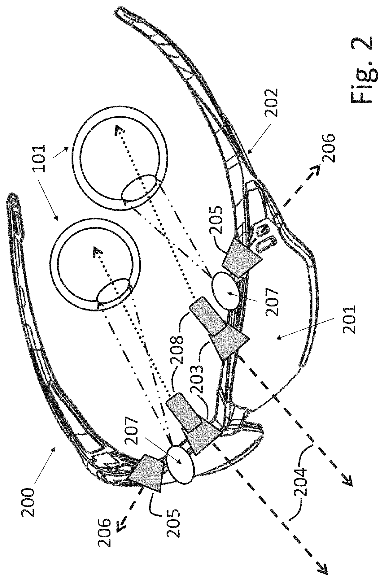
[0045]the display means is shown in FIG. 2. The interior of each screen 201 is a neutral opaque material such as black plastic (not visible in the figure). Retinal projectors 208 project images directly into each eye, through the pupil, to be focused on the retina.

second embodiment

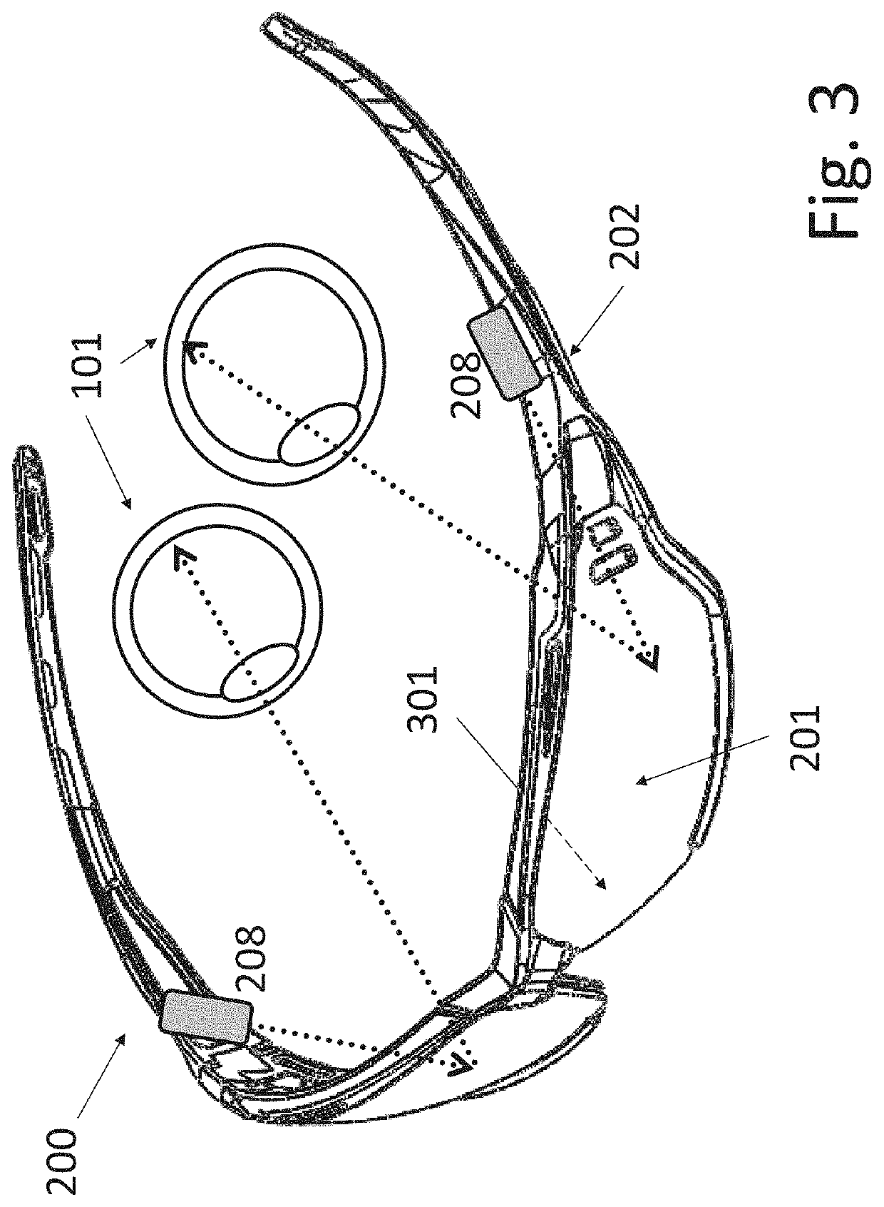
[0046]the display means is shown in FIG. 3. The interior surface of each screen 201 is a mirrored surface 301. Left and right retinal projectors 208 are positioned near the temples on frame 202. Projectors 208 project images onto each mirrored surface. The images are then reflected into each eye. This process is called indirect retinal projection. The advantage of indirect projection is to increase the distance between the image and the eye; human eyes have trouble focusing on objects less than a few inches away.

third embodiment

[0047]the display means is shown in FIGS. 4a, 4b, 5a, and 5b. The interior surface of each screen 201 is a display screen 400 such as an LCD, DLP, or OLED screen.

[0048]The device has left and right eye scanners 207, shown in FIG. 2. Each scanner comprises an eye-tracking sensor. An eye-tracking sensor has an eye-tracking projector, an eye-tracking detector, and a processor (not shown). The eye-tracking projector projects narrow beams of infrared light of a first frequency onto the cornea. The eye-tracking detector detects the location of the pupil and the reflection of the infrared beam from the cornea. By analyzing the relative locations of the pupil and the corneal reflection, the processor determines the direction in which the eye is looking. This technique is known as pupil-center / corneal-reflection (PCCR) eye-tracking, and it is well-known in AR / VR technology and other fields.

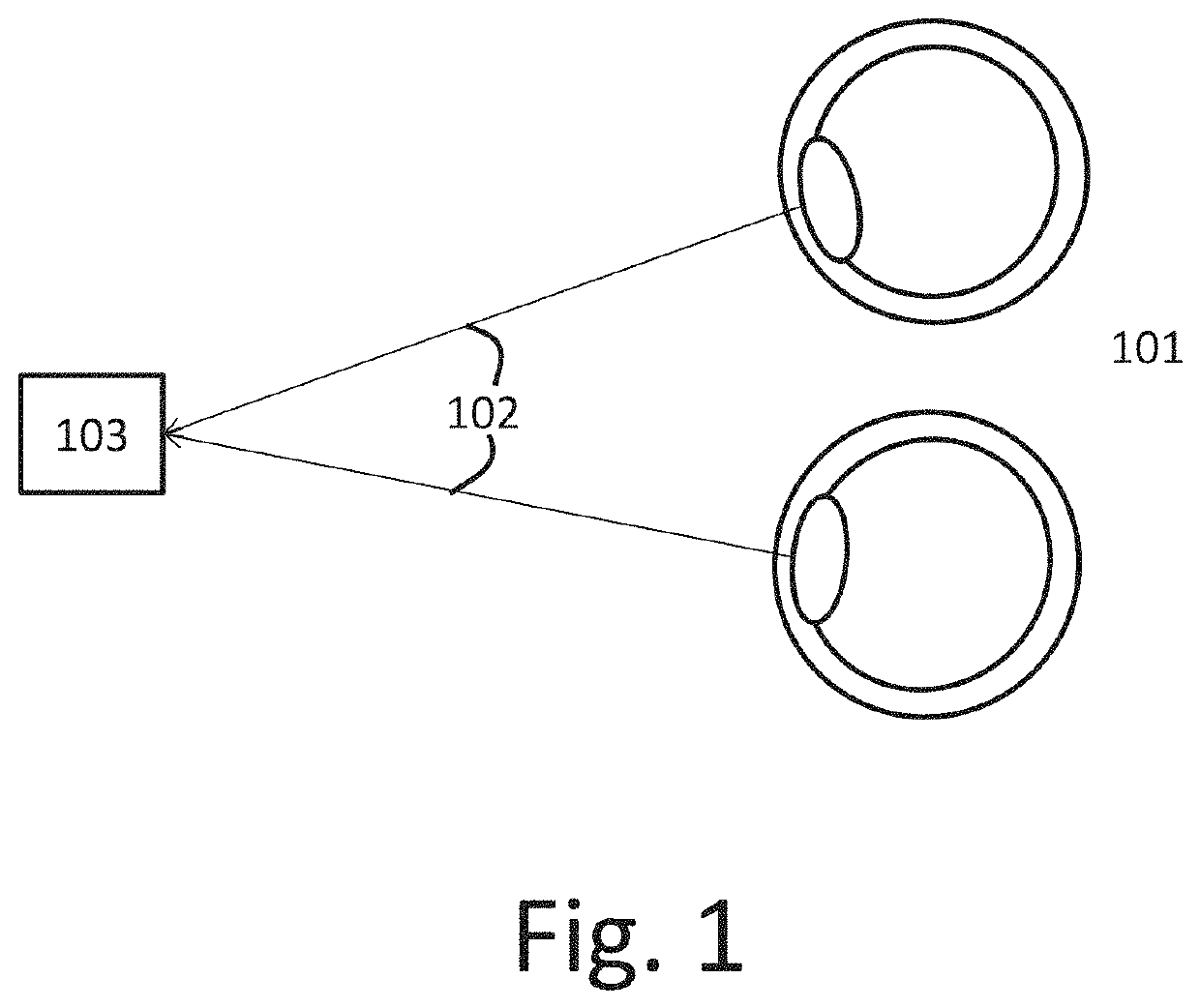
[0049]The processor uses information from the PCCR eye-tracking sensors to determine the line of sight ...


PUM


Abstract

An electronic visual headset useful for purposes of augmented reality, virtual reality, vision correction, and / or vision enhancement. The invention corrects vision impairments such as near-sightedness or far-sightedness. One embodiment uses phakometry cameras to measure the eyes' lenses. An alternative embodiment uses dynamic calibration with test images. The display may be digitally manipulated for correction of night vision, color blindness, or tunnel vision. It may also be enhanced with infrared vision, zoom, etc. Corneal eye-tracking devices and variable-magnification lenses coordinate to resolve vergence-accommodation conflict. An image of the user's eyes is displayed on the exterior of the headset.

Description

1. FIELD OF THE INVENTION[0001]This invention is in the field of optics, particularly for the display of three-dimensional imagery for virtual reality or augmented reality purposes.2. BACKGROUND OF THE INVENTION[0002]Since this invention pertains to vision correction and enhancement, I must review the basics of eye anatomy and the vision process as necessary to understand this invention. The cornea is the clear outer layer of the eye. It has a fixed shape. The cornea protects the underlying iris, the colored annulus. The pupil is a hole in the iris. Behind the pupil is the lens. The lens changes curvature dynamically to focus incoming light. The proper curvature of the lens varies with the distance to the focal plane. The degree of curvature of the lens is known in the art as “accommodation”. Most people's lenses do not work perfectly. The ideal eye focuses images onto the retina, the rear surface of the inner eye, where specialized vision-processing cells and nerves transmit the im...

Claims


Application Information

Patent Timeline
Patent Type & Authority Applications(United States)
IPC IPC(8): H04N13/122H04N13/324H04N13/327H04N13/344G02B27/01G02C7/08
CPCH04N13/122H04N13/324H04N13/327H04N13/344G02B27/0172G02B2027/014G02B27/0179G02B2027/0178G02B2027/0187G02B2027/0138G02B2027/0134G02C7/081G02C11/10H04N13/128G02B27/017
Inventor ZAVOYSKIKH, ANTON
Owner ZAVOYSKIKH ANTON
Why Eureka
Try Eureka