Gas supply warning and communication system

a communication system and gas supply technology, applied in the field of alarm devices, can solve problems such as gas leakage, gas leakage in the cylinder, and the loss of gas flow at a downstream applian

Active Publication Date: 2021-02-18
ADVANCED INTERACTIVE RESPONSE SYST
View PDF1 Cites 1 Cited by
  • Summary
  • Abstract
  • Description
  • Claims
  • Application Information

AI Technical Summary

Problems solved by technology

Such alarms are especially critical in medical gas uses, where a patient's life may be threatened by the interruption of the flow of oxygen or other gas.
There are two types of malfunctions that can cause a loss of gas flow at a downstream appliance.
The first cause is the exhaustion of gas in the cylinder.
A cylinder pressure sensor, however, is ineffective at detecting the second type of gas flow malfunction: malfunctions that occur in the gas lines downstream of the flow valve of a flow regulator.
These downstream malfunctions include the disconnection of a gas line from the flow valve; the disconnection of two joined gas lines; the disconnection of a gas line from an appliance; a leak in a gas line or appliance; and blockages, such as a clog or kink in a gas line.
A gas flow alarm device exists in the prior art, but it cannot warn of all malfunctions occurring downstream of a regulator, or of the depletion of a pressurized gas cylinder or other reservoir.
It cannot sound an alarm if there is a disconnection, leak, or blockage upstream of the alarm device, or if the gas reservoir becomes exhausted.
The duration of the whistle alert is also limited by the amount of gas available to power the whistle.
Furthermore, the whistle can only be perceived by those in the immediate vicinity of the alarm.
It can provide little advance warning of exhaustion of a gas cylinder or other pressurized gas reservoir.
When the pressure of a gas reservoir such as an oxygen cylinder does drop below a predetermined limit, there may be no one available to perceive an alarm indication or to exchange a depleted cylinder for a fresh cylinder.
A common cause of malfunction in a pressurized gas system is the dislodgment of flexible gas tubing from the outlets or connectors to which they are affixed.

Method used


Image

  • Gas supply warning and communication system
  • Gas supply warning and communication system
  • Gas supply warning and communication system

Examples


Embodiment Construction

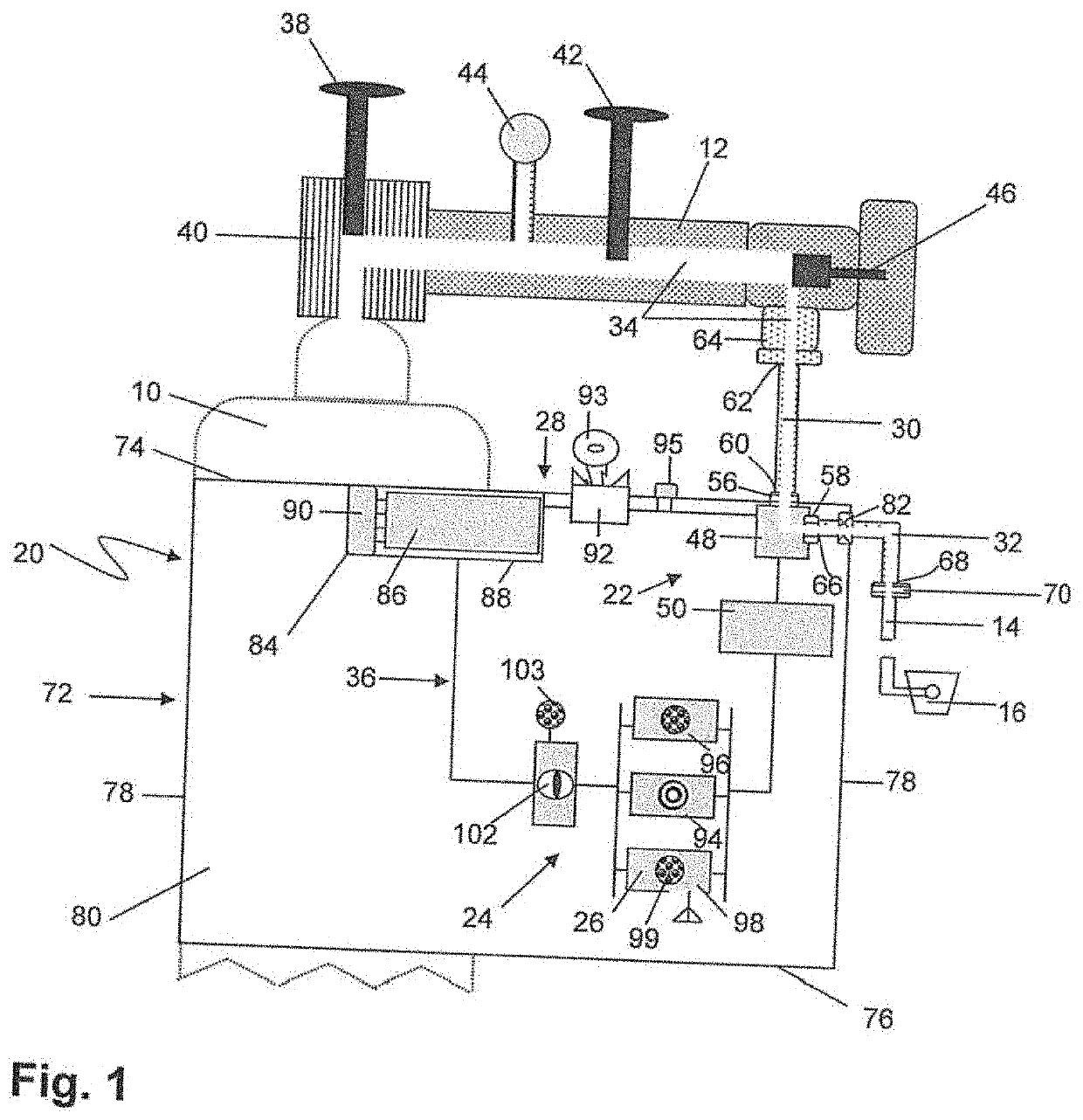
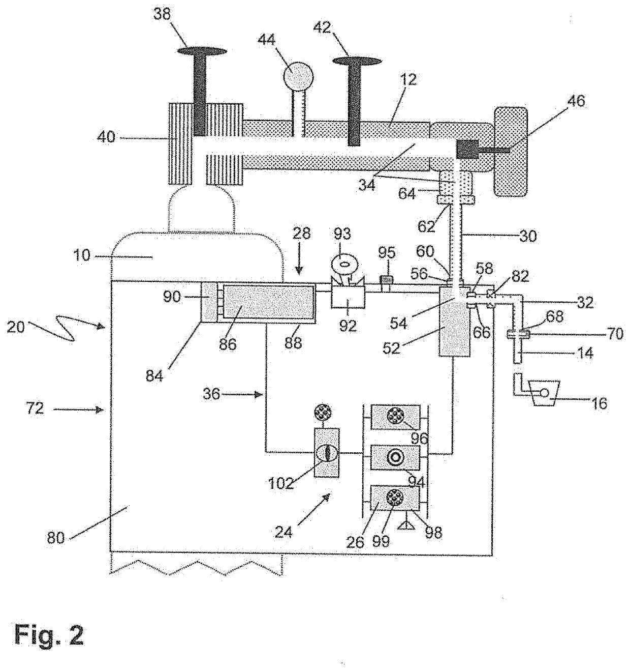
[0084]The pressurized gas system of the present invention include digital displays and control to better and continually monitor the fluid delivered to a patient, as well as deliver alerts and provide automatic changeover to reserve fluid tanks when problems arise with a main tank unlike prior art systems. The pressurized gas system of the present invention can also use a variety of different tubing and connections for various purposes, as described below. A pressurized gas system is defined as a continuous series of vessels in gas-tight interrelationship for conducting gas from a region of high pressure to a region of low pressure. In the example illustrated in FIG. 1, the pressurized gas system is taken to include a gas cylinder 10 or other reservoir, a regulator 12, and all gas lines 14 and appliances 16 downstream of the regulator 12, exclusive of those incorporated into the present invention, which is generally shown at 20.

[0085]The alarm device 20 includes a flow sensing and e...


PUM


Abstract

A fluid supply warning and communication system including a digital regulator in fluid tight engagement with a primary fluid reservoir. A method of using the fluid supply warning and communication system by flowing a fluid from a primary fluid reservoir to an end use appliance and detecting flow rate and pressure of the fluid with a digital regulator. A gas supply warning and communication system including an oxygen flow monitor that monitors SpO2, flow rate, pulse rate, and battery levels. A method of using the gas supply warning and communication system by flowing oxygen from a primary gas reservoir to an end use appliance, and measuring SpO2, flow rate, pulse rate, tank status, and battery levels.

Description

BACKGROUND OF THE INVENTION1. Technical Field[0001]The present invention relates generally to an alarm device to warn of and remedy malfunctions in a pressurized gas system and more specifically to communicate malfunction warnings to remote users, and to allow remote users to control the alarm device.2. Background Art[0002]Pressurized gas systems are used in respiratory therapy, in medical procedures and testing, in the breathing apparatuses of divers and firefighters, and in such industrial fields as welding, heating, ventilation, and air conditioning (HVAC), and plumbing. It is important to provide users of these systems with an alarm to indicate that the supply of gas has been or is about to be exhausted, or that the flow of gas has been interrupted. Pressurized gas alarm systems indicate these conditions by means of audible alarms, alarm lights, and the like. Such alarms are especially critical in medical gas uses, where a patient's life may be threatened by the interruption of ...

Claims


Application Information

Patent Timeline
Patent Type & Authority Applications(United States)
IPC IPC(8): A61M16/00A61M16/06A61M16/16G16H40/40G16H40/67
CPCA61M16/0051A61M16/024A61M16/0666A61M2016/1025G16H40/40G16H40/67A61M16/16A61M16/101A61M16/20A61M16/202A61M2016/0039A61M2205/0205A61M2205/16A61M2205/18A61M2205/3331A61M2205/3569A61M2205/502A61M2205/581A61M2205/587A61M2205/8206A61M2205/8262A61M2209/00A61M2209/01A61M2230/06A61M2230/205A61M2230/432A62B9/006F17C2201/0109F17C2201/056F17C2221/011F17C2223/0123F17C2227/046F17C2250/032F17C2250/034F17C2250/043F17C2250/0443F17C2250/077F17C2270/025G01L19/12A61M2016/0027A61M2205/583A61M2205/50A61M2205/3584A61M2016/0033A61M2205/3306
Inventor OBENCHAIN, VALERIE A.
Owner ADVANCED INTERACTIVE RESPONSE SYST
Why Eureka
Try Eureka