Y-Frame External Bone Fixator

a bone fixator and y-frame technology, applied in the field of bone fixation, can solve the problems that the external fixation system used for extremity surgery in general, and foot surgery in particular, is not believed to have yielded optimal results

Pending Publication Date: 2021-04-01
ATLAS TECH
View PDF10 Cites 0 Cited by
  • Summary
  • Abstract
  • Description
  • Claims
  • Application Information

AI Technical Summary

Benefits of technology

The patent text describes mounting hardware that allows for adjustability in multiple degrees of freedom of translation and rotation. One example of this mounting hardware is a pin-holding assembly that includes a clamping bolt. Another example is a yoke with a complementary feature that engages with repeated features on an arm or other component. The mounting hardware can be used to securely hold pins or other components in place. The technical effects of this patent include improved mounting hardware that allows for greater flexibility and secure mounting of components.

Problems solved by technology

The technical problem addressed in this patent is to improve the design features of external fixation systems for orthopedic medicine, particularly for foot surgery, to make them simpler and more user-friendly for surgeons and easier for patients to understand. Current external fixators, such as the Ilizarov frame, are bulky and not optimal for foot surgery. The patent aims to create a simpler and more efficient external fixation system for foot surgery and other extremity surgeries.

Method used


Image

  • Y-Frame External Bone Fixator
  • Y-Frame External Bone Fixator
  • Y-Frame External Bone Fixator

Examples


Embodiment Construction

[0054]Directional and spatial anatomical terminology that may be used herein is well known to those skilled in the art. For instance, the term “medial” typically means closer to the midline of the body, and “lateral” typically means farther from the midline of the body. Further terms, such as “proximal”, “distal”, “anterior”, “posterior”, “superior”, “inferior”, and other such terms shall have their common and ordinary meanings in the art.

Basic Y-Frame

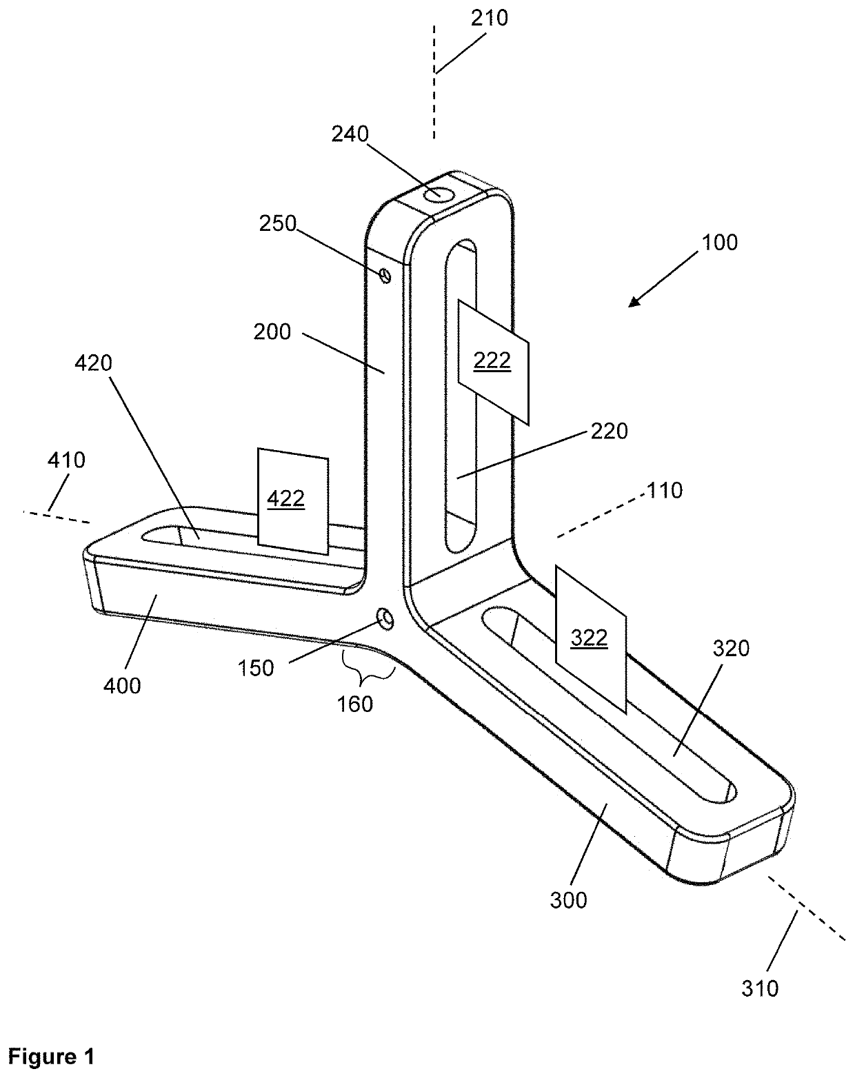
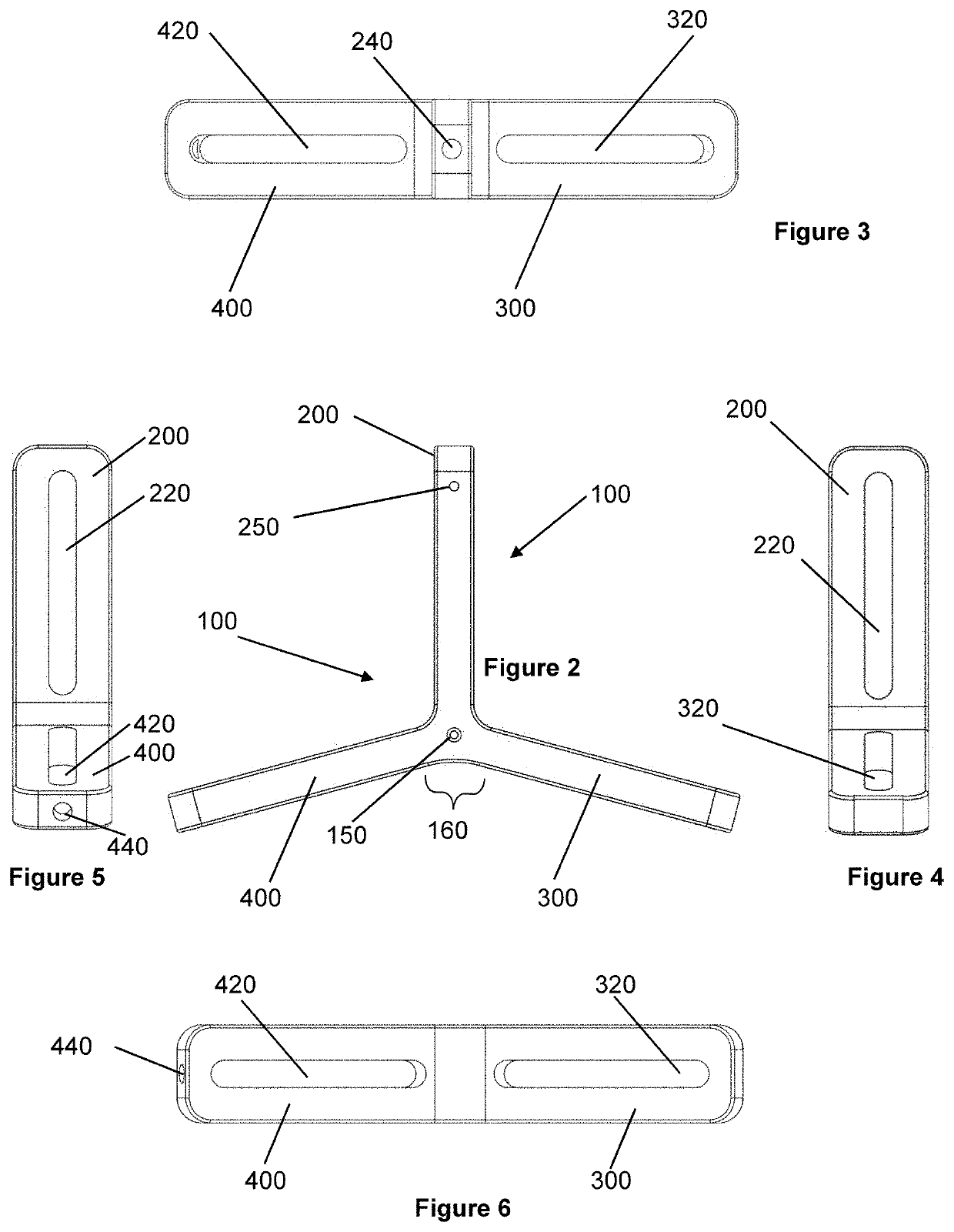
[0055]Referring now to FIGS. 1-6, an embodiment of the invention comprises a Y-frame 100. FIG. 1 is a perspective view. FIGS. 2-6 are, respectively, views from the side, top, anterior, posterior and bottom. In the embodiment that is shown in FIG. 1, the Y-frame 100 is substantially rigid and the Y-frame 100 itself is non-adjustable. As illustrated, Y-frame 100 may have an axis 110 and an axis hole 150 as discussed herein. In an embodiment, the Y-frame has three arms, designated as a superior arm 200, an anterior arm 300, and a posterio...


PUM


Abstract

In an embodiment of the invention, a fixator for fixating bone fractures includes a Y-frame having superior, anterior and posterior arms. The arms may be slotted and may accept mounting hardware for supporting fixation pins or transfixion pins. Various components of mounting hardware may be able to be adjusted either in discrete steps or in continuous manner, for various degrees of either translation or rotation. The Y-frame may be rigid, or may have joints that allow either angulation or arm-twisting adjustment. Arms may be provided joinable interchangeably to a hub. A kit of such parts may be provided.

Description


Claims


Application Information

Patent Timeline
Owner ATLAS TECH
Why Eureka
Try Eureka