System and method for directional drilling a borehole with a rotary drilling system

a drilling system and rotary drilling technology, applied in the direction of directional drilling, artificial islands, foundation engineering, etc., can solve the problems of pad/actuator size too large to erode the formation where the system is applied, and the bit may veer o

Active Publication Date: 2009-02-19
SCHLUMBERGER TECH CORP
View PDF98 Cites 43 Cited by
  • Summary
  • Abstract
  • Description
  • Claims
  • Application Information

AI Technical Summary

Benefits of technology

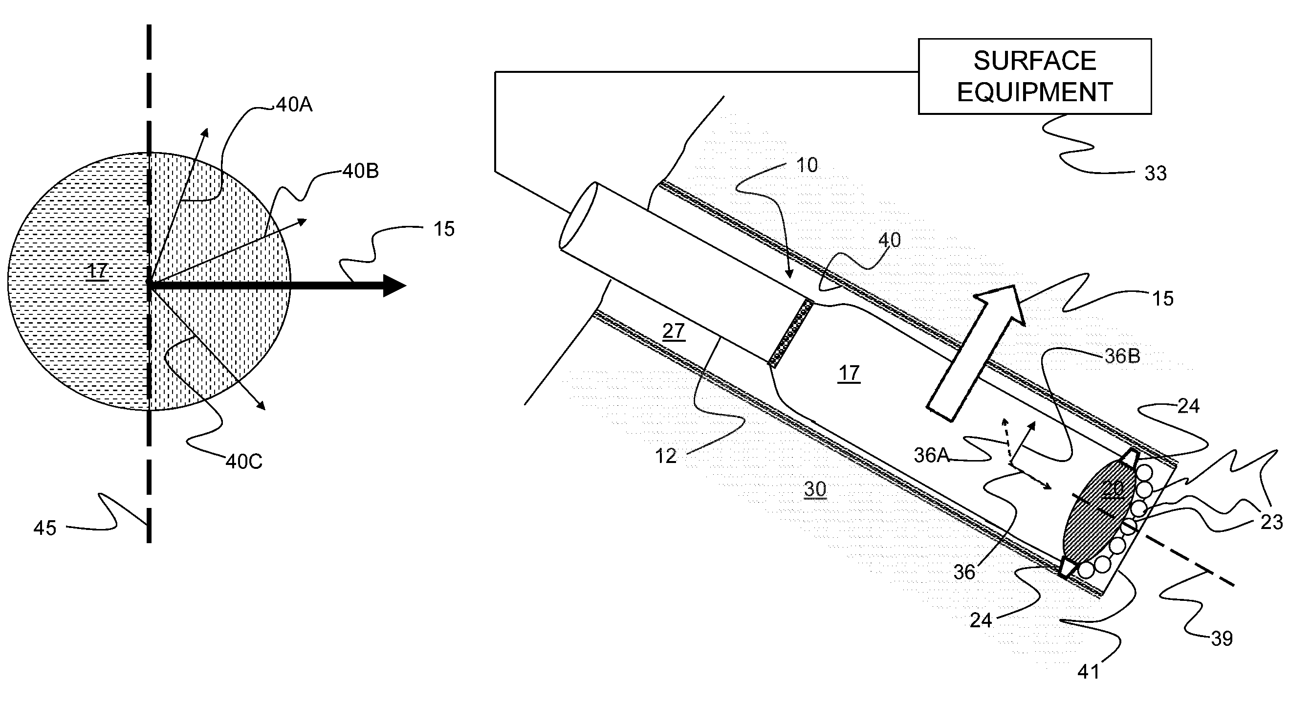
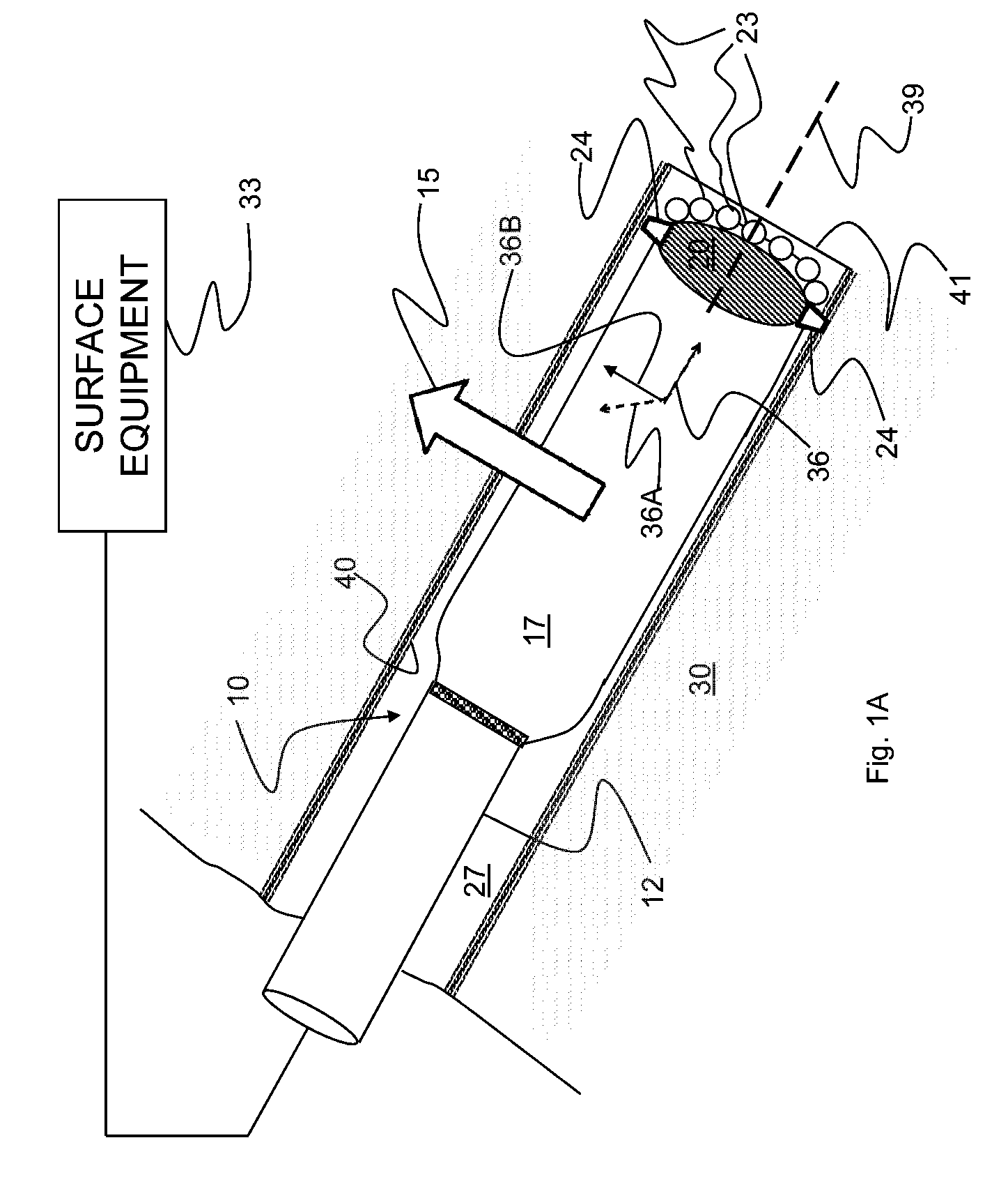
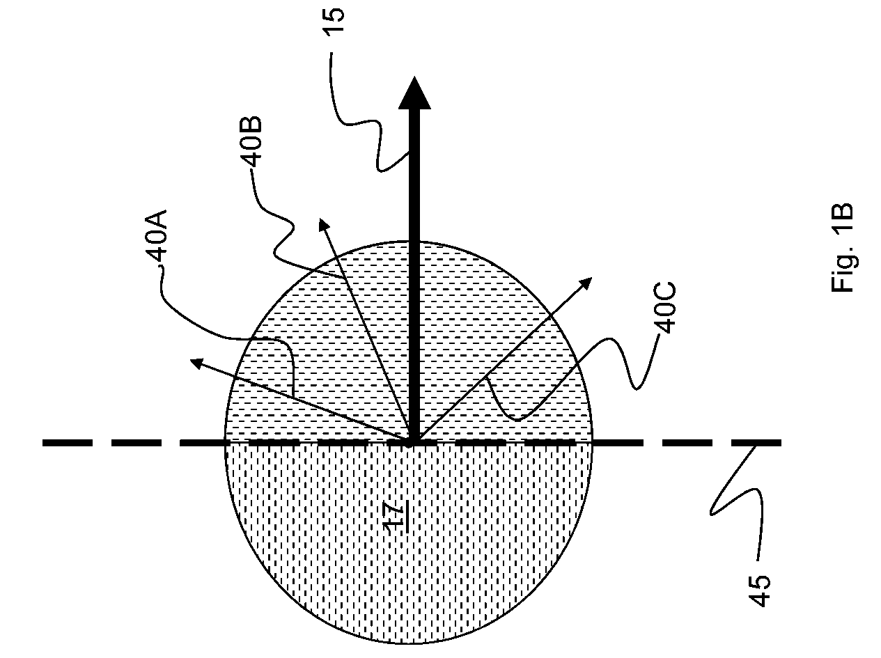
[0026]This disclosure relates in general to a method and a system for controlling a rotary drilling system to directionally drill a borehole through an earth formation, the rotary drilling system comprising a drill string and a drill bit, wherein the drill bit is rotated by the drill string against the earth formation. More specifically, but not by way of limitation, embodiments of the present invention provide for controlling the motion of the drilling system in a borehole being drilled by the system and/or the reaction forces between the d

Problems solved by technology

For example, in a vertical drilling operation, the drill bit may veer off of a planned vertical drilling trajectory because of the unpredictable nature of the formations being penetrat

Method used


Image

  • System and method for directional drilling a borehole with a rotary drilling system
  • System and method for directional drilling a borehole with a rotary drilling system
  • System and method for directional drilling a borehole with a rotary drilling system

Examples


Embodiment Construction

[0059]The ensuing description provides exemplary embodiments only, and is not intended to limit the scope, applicability or configuration of the disclosure. Rather, the ensuing description of the exemplary embodiments will provide those skilled in the art with an enabling description for implementing one or more exemplary embodiments. Various changes may be made in the function and arrangement of elements of the specification without departing from the spirit and scope of the invention as set forth in the appended claims.

[0060]Specific details are given in the following description to provide a thorough understanding of the embodiments. However, it will be understood by one of ordinary skill in the art that the embodiments may be practiced without these specific details. For example, systems, structures, and other components may be shown as components in block diagram form in order not to obscure the embodiments in unnecessary detail. In other instances, well-known processes, techni...


PUM


Abstract

This disclosure relates in general to a method and a system for directionally drilling a borehole with a rotary drilling system. More specifically, but not by way of limitation, methods and system provide for controlling motion of the rotary drilling system in the borehole when a side force is applied to the drilling system to bias or focus the motion so that the drilling system directionally drills the borehole through an earth formation. In certain aspects, side cutting of a sidewall of the borehole by a drill bit under an applied side force is controlled by a geostationary element to provide for directional side cutting and, as a result, directional drilling of the borehole through the earth formation. In other aspects, a non-concentrically coupled gauge pad assembly may rotate with the drilling system and bias or focus the applied side force.

Description

[0001]This application claims the benefit of and is a continuation-in-part of U.S. application Ser. No. 11 / 839,381 filed on Aug. 15, 2007, which is incorporated by reference in its entirety for all purposes.[0002]This application is related to the U.S. patent application Ser. No. ______, filed on the same date as the present application, entitled “STOCHASTIC BIT NOISE CONTROL” (temporarily referenced by Attorney Docket No. 57.0825 US CIP), which is incorporated by reference in its entirety for all purposes.[0003]This application is related to the U.S. patent application Ser. No. ______, filed on the same date as the present application, entitled “DRILL BIT GAUGE PAD CONTROL” (temporarily referenced by Attorney Docket No. 57.0831 US CIP), which is incorporated by reference in its entirety for all purposes.[0004]This application is related to U.S. patent application Ser. No. ______, filed on the same date as the present application, entitled “METHOD AND SYSTEM FOR STEERING A DIRECTION...

Claims


Application Information

Patent Timeline
IPC IPC(8): E21B44/02
CPCE21B7/06
Inventor SHEPPARD, MICHAEL CHARLESJOHNSON, ASHLEY BERNARDDOWNTON, GEOFF
Owner SCHLUMBERGER TECH CORP
Why Eureka
Try Eureka