Enhanced cage insertion device

a cage and cage technology, applied in the field of enhanced cage insertion devices, can solve the problems of high proinflammatory cytokines, high risk of patient operative time, and inability to effectively so as to facilitate insertion and placement of instruments, increase patient risk and operative time, and prevent patient stress-inducing engagement

Active Publication Date: 2015-03-17
DEPUY SYNTHES PROD INC
View PDF15 Cites 44 Cited by
  • Summary
  • Abstract
  • Description
  • Claims
  • Application Information

AI Technical Summary

Benefits of technology

[0021]In accordance with the present invention, there is provided a cage insertion instrument adapted to insert an intervertebral interbody cage through a conventional spinal surgery approach (such as ALIF, TLIF, PLIF, or LLIF). In preferred embodiments, this instrument includes a cannulated sheath comprising a) a proximal cannulated portion, and b) a distal cannulated sheath that surrounds the cage during insertion into the disc space. The sheath shields the textured surface of the cage from the vertebral body endplates, thereby preventing their stress-inducing engagement therewith. The sheath has an expandable tapered or bulleted distal tip to ease insertion and placement of the instrument (and cage) within the disc space. Once the cage is inserted to its proper depth in the disc space, the sheath can be refracted while the cage is held stationary by a threaded rod disposed within the sheath. This retraction exposes the sharp, textured surface of the cage for engagement with the vertebral endplates.
[0022]Therefore, the inserter of the present invention provides a number of benefits to the spinal surgeon. In particular, it provides initial distraction of the disc space, improves the ease of insertion and placement of an intervertebral spacer, minimizes damage to the spacer and / or endplate during spacer insertion and placement, provides a means to deliver and contain graft within the spacer and surrounding disc space, and reduces the secondary positioning and time required to implant a spacer.
[0023]The sheath also provides a delivery and containment means for bone graft and / or BMP's, bone graft can be placed either within the cage, or distal or proximal to the cage for simultaneous delivery therewith. This containment means prevents leakage during insertion into the body, during placement into the disc space, and during final deployment into the disc space.

Problems solved by technology

In other instances of DDD, genetic factors or apoptosis can also cause the cells within the nucleus pulposus to emit toxic amounts of these cytokines and MMPs.
In some instances, the pumping action of the disc may malfunction (due to, for example, a decrease in the proteoglycan concentration within the nucleus pulposus), thereby retarding the flow of nutrients into the disc as well as the flow of waste products out of the disc.
This reduced capacity to eliminate waste may result in the accumulation of high levels of proinflammatory cytokines and / or MMPs that may cause nerve irritation and pain.
As DDD progresses, toxic levels of the cytokines and MMPs present in the nucleus pulposus begin to degrade the extracellular matrix.
In particular, the MMPs (as mediated by the cytokines) begin cleaving the water-retaining portions of the proteoglycans, thereby reducing their water-retaining capabilities.
This degradation leads to a less flexible nucleus pulposus, and so changes the loading pattern within the disc, thereby possibly causing delamination of the annulus fibrosus.
These changes cause more mechanical instability, thereby causing the cells to emit even more cytokines, typically thereby upregulating MMPs.
As this destructive cascade continues and DDD further progresses, the disc begins to bulge (“a herniated disc”), and then ultimately ruptures, causing the nucleus pulposus to contact the spinal cord and produce pain.
However, these cages are difficult to insert because of the interference fit that is required for intervertebral space distraction.
In addition, the reinforced PEEK material that makes up the teeth is brittle and so is susceptible to breakage when applying impact or torque loads to the implant.
Titanium has the disadvantage of being radiopaque (which can interfere with fusion assessment on x-ray) while also having a high modulus of elasticity (which can stress shield the bone graft).
Injection molded CFRP is very brittle and susceptible to fracture during insertion.
Unreinforced PEEK is much less brittle but also weaker than carbon-filled PEEK, requiring thicker-walled designs (diminishing space for bone graft).
In summary, the insertion of both smooth and toothed intervertebral cages has proven to be problematic due to high resistance forces (friction) and interference fit of the cage and intervertebral space.
Whereas toothed cages are difficult to insert, cages with smooth upper and lower surfaces have demonstrated undesirable migration.
Current injection-molded PEEK or carbon fiber reinforced PEEK (CFRP) cages are difficult to insert because of the interference fit between the textured / spiked surfaces of the implant and the bony endplates.
The difficulty of direct, unshielded cage insertion and final positioning in the disc space also increases the likelihood of bony endplate damage, as the disc space preparation, FSU distraction forces and insertion trajectory are variable.
Consistent and accurate placement of the posteriorly inserted spinal fusion cages is difficult because light tamping and impaction are employed for final positioning.
It has been found that the graft and / or BMP frequently drips or falls out of the graft retaining pockets.
The uncontrolled delivery of the BMP / graft can irritate adjacent tissues and prompt bone formation in undesired locations including heterotopic bone.
Many spinal fusion procedures require either pre and or post packing of the disc space, thereby increasing patient risk and operative time.

Method used


Image

  • Enhanced cage insertion device
  • Enhanced cage insertion device
  • Enhanced cage insertion device

Examples


Embodiment Construction

[0052]In some embodiments, the instrument comprises two, three, four or more components.

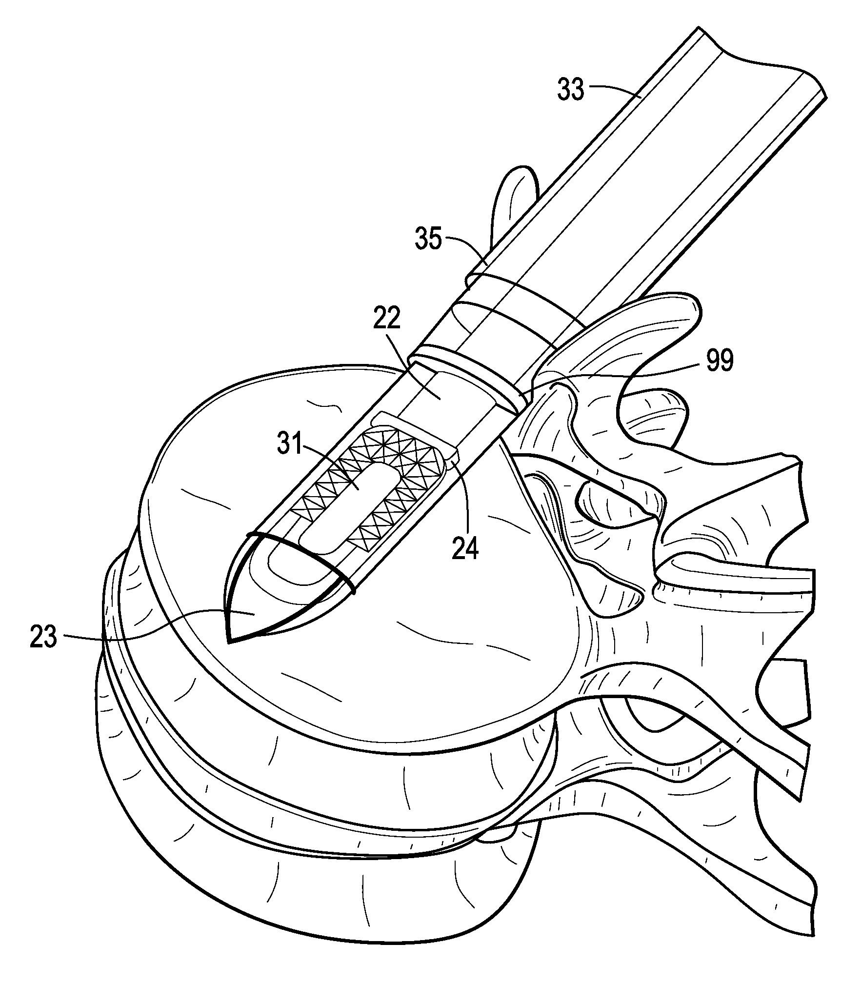
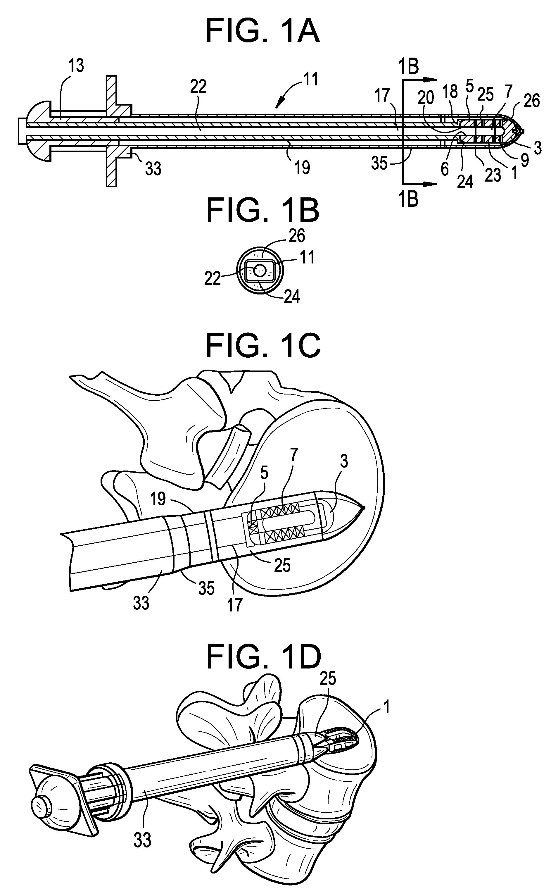
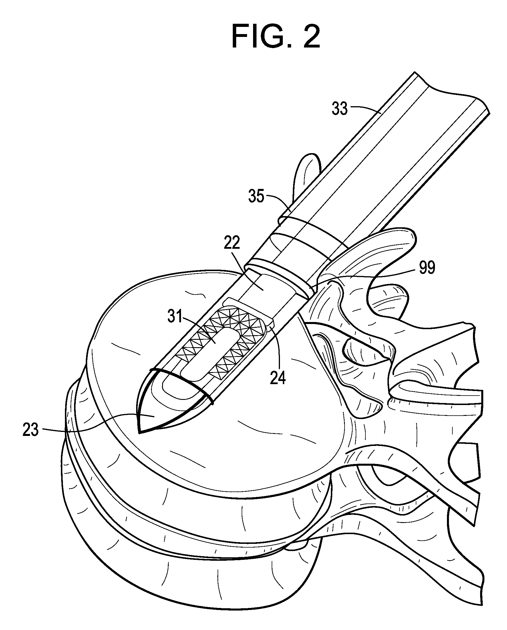
[0053]Now referring to FIGS. 1A-1D, there is provided an assembly of the present invention in which the inserter has four components: a sheath, a cannulated rod holder, a rod and a docking port. In particular, the assembly comprises:[0054]a) an intervertebral fusion cage 1 having a leading end 3, a trailing end 5 having a threaded hole 6, an upper face 7 and a lower face 9, and[0055]b) an inserter 11 comprising:[0056]i) a cannulated rod holder 13 having a bore therethrough and a distal end portion 17 having a distal end 18 bearing against the trailing end of the cage,[0057]ii) a rod 22 received within the bore of the cannulated rod holder, the rod having a threaded distal end 20 mating with the threaded hole of the cage,[0058]iii) a cannulated sheath 19 adapted to receive the cannulated rod holder, the sheath having a plurality of sheath portions 23,25 extending distally therefrom,[0059]iv) a doc...


PUM


Abstract

A method of delivering a fusion cage to an intervertebral disc space bounded by adjacent vertebral endplates, comprising the step of delivering the fusion cage into the disc space without contacting its teeth to the vertebral endplates during delivery, wherein a sheath is interposed between a cage surface and the endplates to prevent contact therebetween during delivery.

Description

BACKGROUND OF THE INVENTION[0001]The natural intervertebral disc contains a jelly-like nucleus pulposus surrounded by a fibrous annulus fibrosus. Under an axial load, the nucleus pulposus compresses and radially transfers that load to the annulus fibrosus. The laminated nature of the annulus fibrosus provides it with a high tensile strength and so allows it to expand radially in response to this transferred load.[0002]In a healthy intervertebral disc, cells within the nucleus pulposus produce an extracellular matrix (ECM) containing a high percentage of proteoglycans. These proteoglycans contain sulfated functional groups that retain water, thereby providing the nucleus pulposus with its cushioning qualities. These nucleus pulposus cells may also secrete small amounts of cytokines as well as matrix metalloproteinases (MMPs). These cytokines and MMPs help regulate the metabolism of the nucleus pulposus cells.[0003]In some instances of degenerative disc disease (DDD), gradual degenera...

Claims


Application Information

Patent Timeline
Patent Type & Authority Patents(United States)
IPC IPC(8): A61B17/58A61F2/00A61B17/60A61F2/30A61F2/44A61F2/46
CPCA61F2/4611A61F2/4455A61F2/446A61F2/4465A61F2002/30034A61F2002/30092A61F2310/00239A61F2002/30731A61F2002/4475A61F2002/448A61F2310/00017A61F2310/00023A61F2002/30604A61F2002/30032A61F2002/30593A61F2/447A61F2/4601A61F2002/30331
Inventor VOELLMICKE, JOHN C.O'NEIL, MICHAEL J.SHAW, DEREKGRINBERG, ALEXANDER
Owner DEPUY SYNTHES PROD INC
Why Eureka
Try Eureka