Terminal clamp with insertion funnel

Active Publication Date: 2021-04-01
BJB GMBH & CO KG
View PDF0 Cites 1 Cited by
  • Summary
  • Abstract
  • Description
  • Claims
  • Application Information

AI Technical Summary

Benefits of technology

[0015]This way it is assured that slanted surfaces that taper towards each other in a funnel shape facilitate a centering of the conductor along a direction of the contact longitudinal axis or longitudinal axis of the terminal clamp or longitudinal axis of the contact cage when the conductor is inserted into the terminal clamp.
[0016]It is furthermore provided that the cage ceiling includes an engagement opening for an opening tool in a transition portion to a respective side wall wherein the engagement opening facilitates access to the spring element.
[0017]It is furthermore provided that the cage ceilin

Problems solved by technology

The essential disadvantage of the prior art is that a space is required between the two opposite connection clamps wherein

Method used


Image

  • Terminal clamp with insertion funnel
  • Terminal clamp with insertion funnel
  • Terminal clamp with insertion funnel

Examples


Example

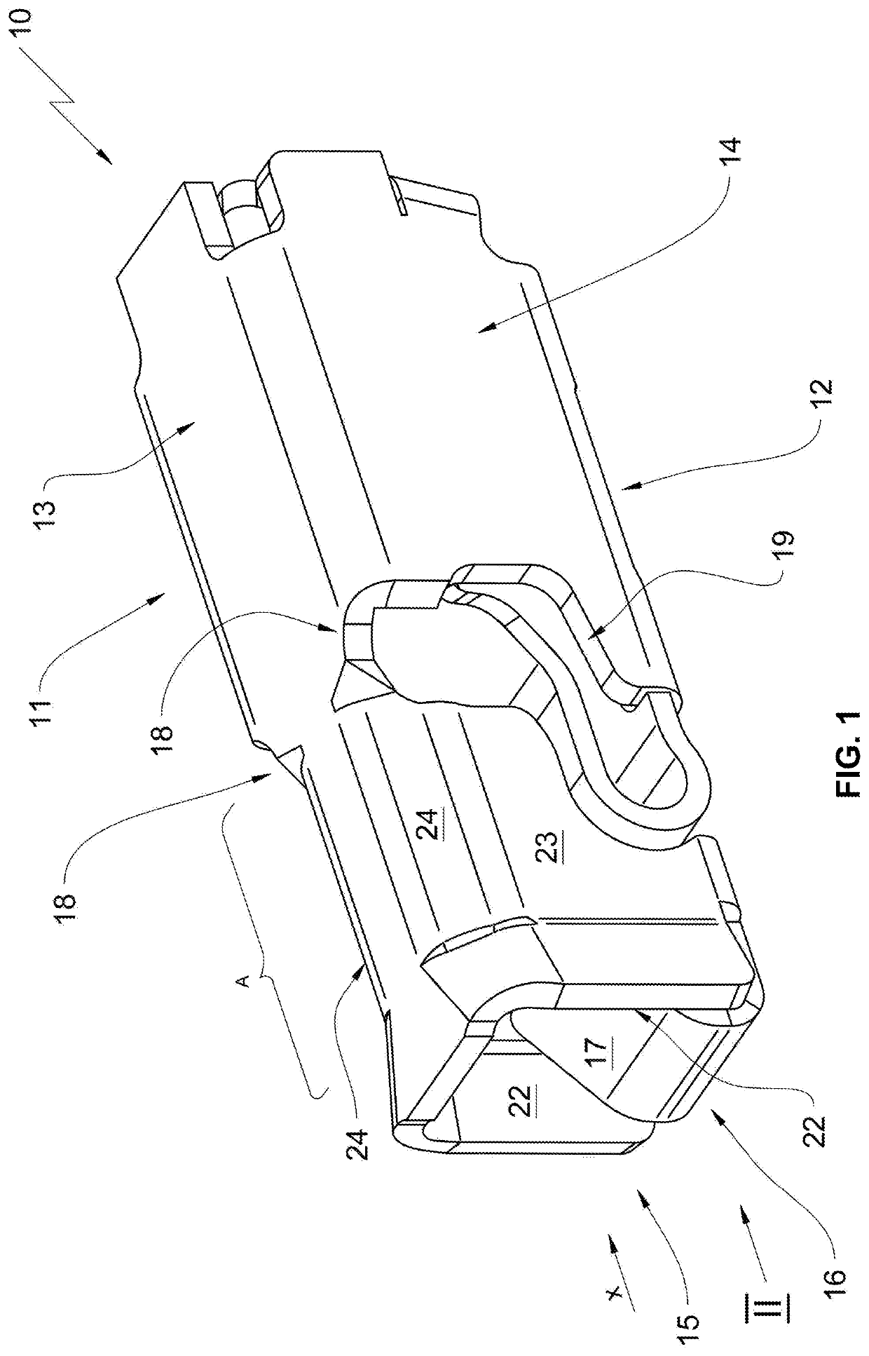
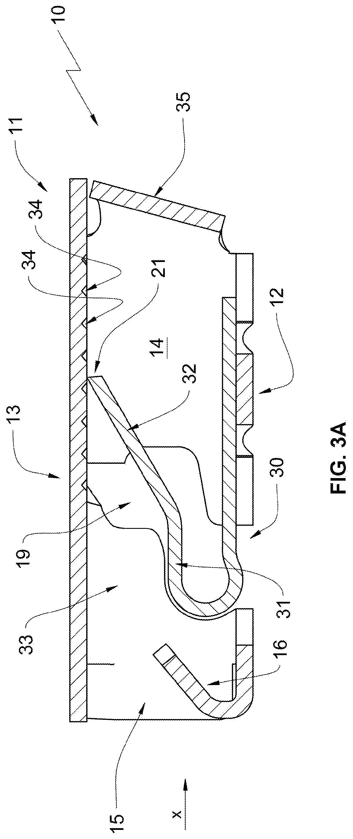
[0027]A terminal clamp according to the invention is provided with reference numeral 10 in the drawing figures.

[0028]The terminal clamp 10 is illustrated in FIG. 1 in a perspective view. The terminal clamp 10 according to the invention is e.g. a surface mounted device (SMD) which is applied to circuit boards not illustrated herein in order to provide a power supply and control signal supply for electrical and electronic components arranged on the circuit board.

[0029]The terminal clamp 10 according to the invention is a terminal clamp 10 without housing, thus a terminal clamp 10 that is not enveloped by a housing made from insulation material.

[0030]The terminal clamp 10 according to FIG. 1 includes a contact cage 11 that essentially includes an outer contour configured as a cuboid. The contact cage 11 is formed by a cage floor 12, a cage ceiling 13 and two cage side walls 14. Thus the cage side walls 14 are arranged opposite to one another and connect the cage floor 12 with the cage ...


PUM


Abstract

A terminal clamp including a contact cage including a cage floor, a cage ceiling and two cage side walls that are arranged opposite to each other and respectively connect the cage floor with the cage ceiling, wherein the cage floor, the cage ceiling and the two cage side walls form an inner enveloping surface in combination and envelop a conductor receiving cavity; a clamping device formed by at least one spring element and a reaction bearing, the clamping device configured to support and electrically contact an electrical conductor in the conductor receiving cavity; a frontal conductor insertion opening that is enveloped by the two cage side walls, the cage ceiling and the cage floor, wherein the electrical conductor is insertable through the conductor insertion opening into the conductor receiving cavity and feedable to the clamping device; a contact cage longitudinal axis oriented in the conductor insertion direction;

Description

RELATED APPLICATIONS[0001]This application claims priority from German patent application DE10 2019 125 895.2, filed on Sep. 26, 2019, which is incorporated in its entirety by this reference.FIELD OF THE INVENTION[0002]The invention relates to a terminal clamp with a contact cage including a cage floor, a cage ceiling and two cage side walls that are arranged opposite to each other and respectively connect the cage floor with the cage ceiling wherein the cage floor, the cage sealing and the two opposite side walls form an enveloping surface in combination and envelop a conductor receiving space; a clamping device formed by at least one spring element and a reaction bearing configured to support and electrically contact an electrical conductor; a front side conductor insertion opening that tis enveloped by the cage side walls, the cage ceiling and the cage floor wherein the electrical conductor is insertable through the conductor insertion opening into the conductor receiving cavity ...

Claims


Application Information

Patent Timeline
IPC IPC(8): H01R4/48
CPCH01R4/4818H01R4/48185H01R12/515H01R4/48275
Inventor BAUMEISTER, OLAFHENRICI, PHILIPP
Owner BJB GMBH & CO KG
Why Eureka
Try Eureka