

Turbomachine combustion chamber
- Summary
- Abstract
- Description
- Claims
- Application Information
AI Technical Summary
Benefits of technology
Problems solved by technology
Method used
Image

Examples
Embodiment Construction
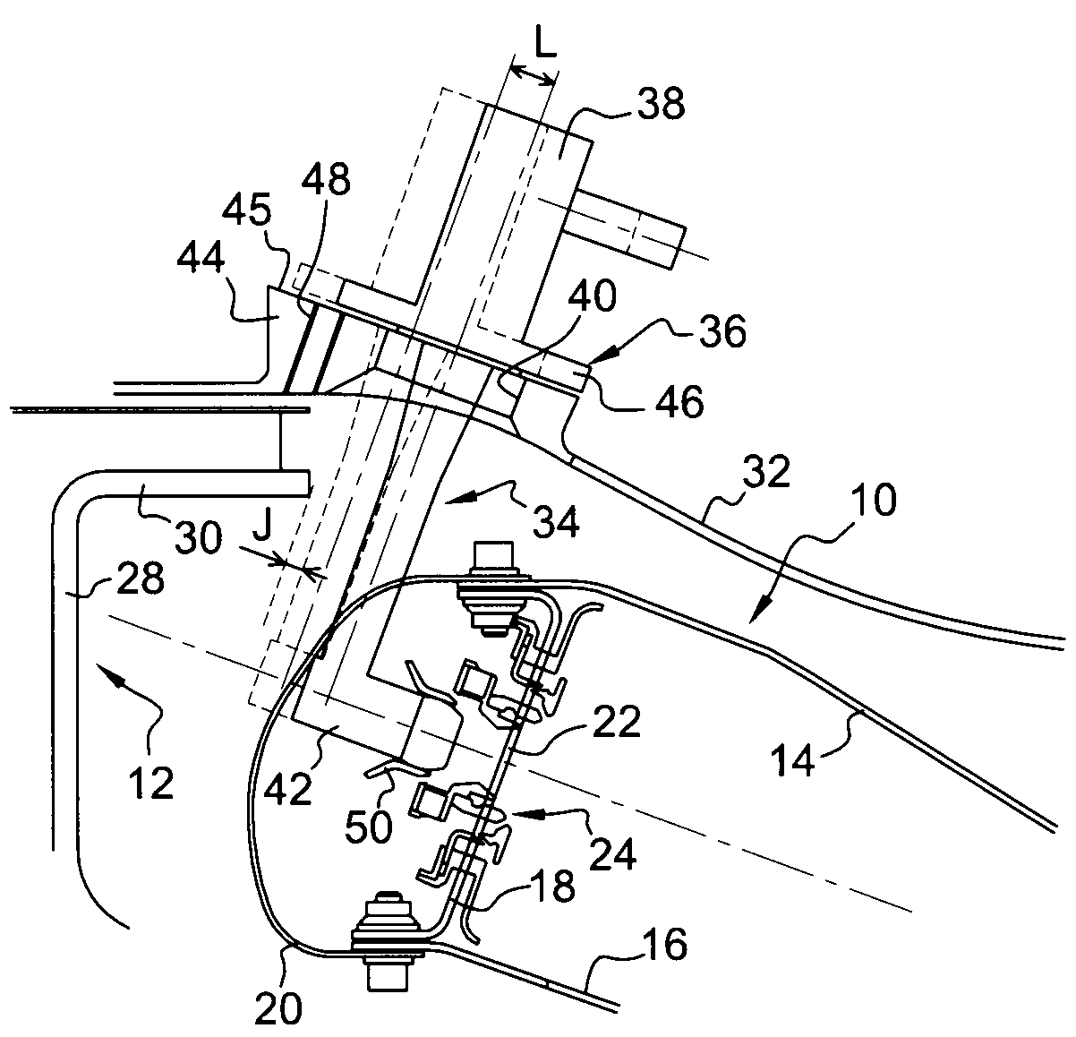
[0035]FIG. 1 shows an annular combustion chamber 10 of a turbomachine such as an airplane turboprop or turbojet, the chamber 10 being arranged at the outlet from a diffuser 12, which is in turn situated at the outlet from an axial-centrifugal compressor that is not shown.
[0036]The chamber 10 has an outer wall 14 forming a body of revolution and an inner wall 16 also forming a body of revolution, which walls are connected together at an upstream end by an annular chamber end wall 18.
[0037]An annular fairing 20 is fastened to the upstream ends of the chamber chambers 14, 16, and 18, and it includes air-passing orifices in alignment with openings 22 in the chamber end wall 18, each having a mixer 24 mounted therein to mix the air coming from the diffuser 12 with fuel delivered by fuel injectors 34.
[0038]The diffuser 12 has a substantially radial annular portion 28 with its inner periphery connected to the outlet from the compressor and with its outer periphery connected to the upstream...
PUM
 Abstract
Description
Claims
Application Information