
Milling tool

a technology of milling tools and tools, which is applied in the direction of earth drilling, sealing/packing, and well accessories, etc., can solve the problems of large potential environmental threat, interference with both milling operations, and unproductive or abandoned wells which are not permanently plugged, so as to eliminate the magnetic attraction

Active Publication Date: 2021-05-20
SWARFIX AS
View PDF0 Cites 1 Cited by
  • Summary
  • Abstract
  • Description
  • Claims
  • Application Information

AI Technical Summary

Benefits of technology

This patent is about a milling tool used for removing metal cuttings from a workpiece. The tool has a scrape end that is located at the end closest to the milling section. This end is made up of a cylinder-shaped non-magnetic element that prevents the metal cuttings from getting attached to it. This helps to keep the tool clean and allows for easier removal of the metal cuttings from the workpiece. This invention is important because it improves the efficiency and accuracy of the milling process.

Problems solved by technology

Unproductive or abandoned wells which are not permanently plugged represents a large potential environmental threat.
The milling operation produces large amounts of metal cuttings which may interfere with both the milling operation itself and the subsequent plug cementing operation.

Method used


Image

  • Milling tool
  • Milling tool
  • Milling tool

Examples


Embodiment Construction

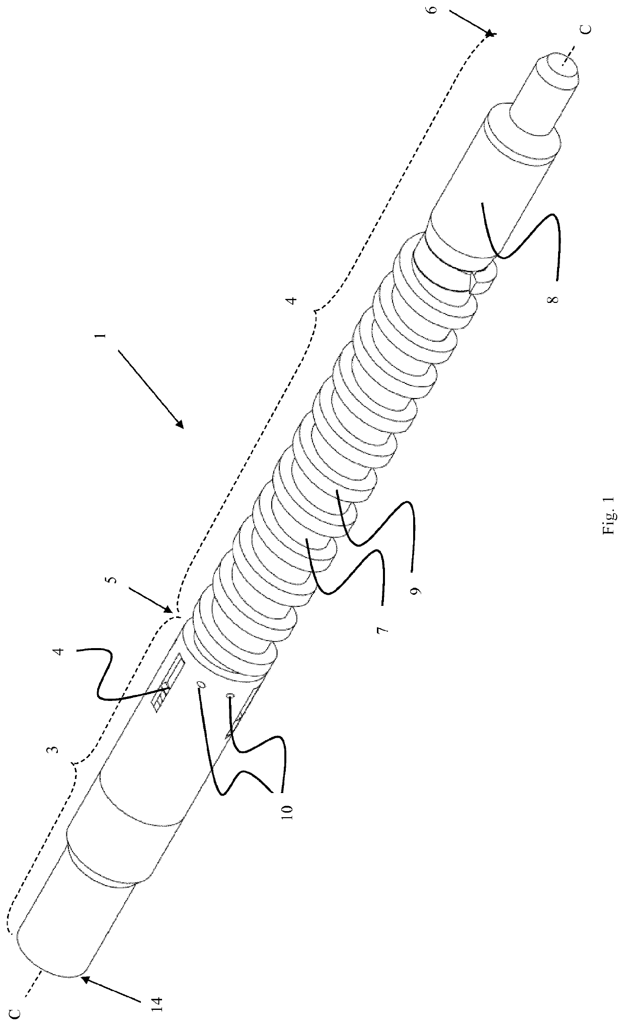
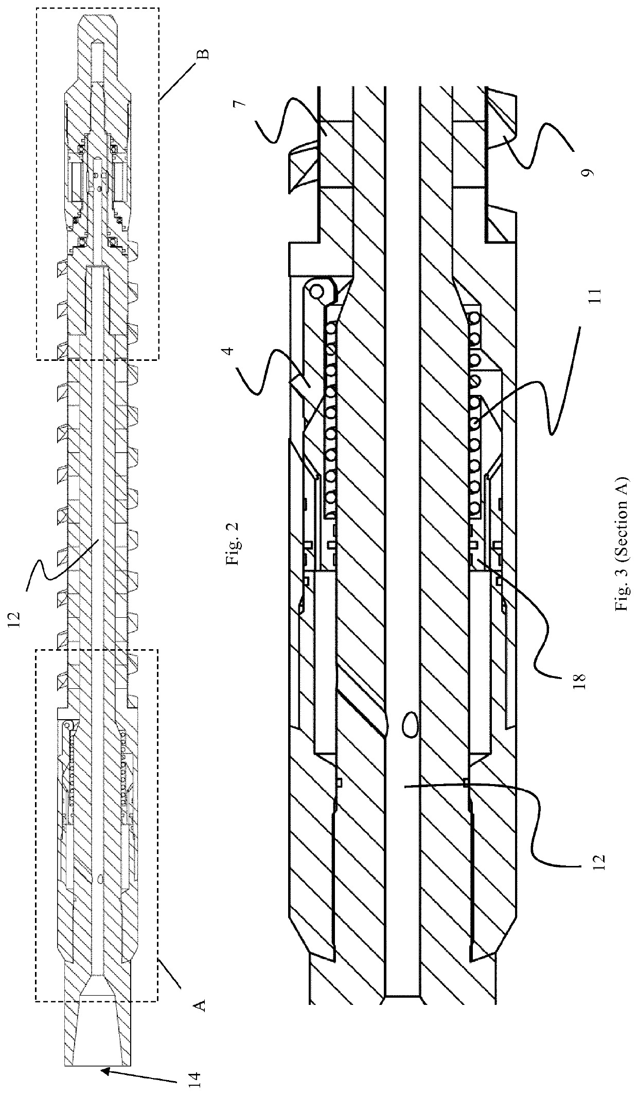
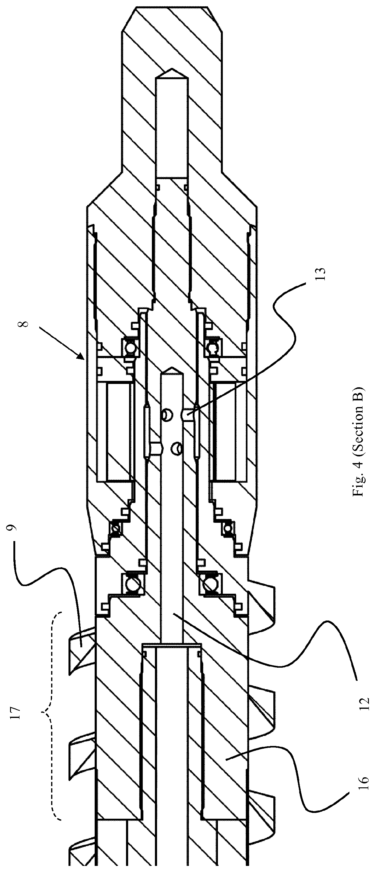
[0044]A first embodiment of a milling tool according to the present invention is shown in FIGS. 1-4.

[0045]The inventive milling tool is particularly suitable for section milling in plug and abandonment operations (P&A). As opposed to the prior art milling tools, the milling tool according to the invention is able to perform milling in a downwards direction while at the same time pushing / guiding produced metal cutting further down in the well bore. Further, the present milling tool avoids or alleviates the interference of produced metal cuttings with the milling itself, i.e. the metal cuttings are prevented from nesting / clogging the cutters.

[0046]The milling tool comprises a milling section 2 and a metal cuttings removal section 3. The milling section features four radially arranged cutters 4 (i.e. milling elements) suitable for milling a wellbore casing. The cutters may move between a passive and an active position. In the passive position, as shown in FIGS. 1-3, the cutters are ret...


PUM


Abstract

The present invention provides a milling tool (1) for a wellbore, comprising a milling section (2) and a metal cuttings removal section (3), the milling section (2) comprises radially arranged milling elements (4); and the metal cuttings removal section (3) has a first end (5) and a second end (6) and comprises a cylinder-shaped magnetic element (7), a rotation generating device (8) and a helix-shaped longitudinal guide element (9), wherein the first end (5) is connected to the milling section; the helix-shaped longitudinal guide element (9) is arranged around the cylinder-shaped magnetic element (7); the rotation generating device (8) is operably connected to the cylinder-shaped magnetic element (7) or the helix-shaped longitudinal guide element (9); wherein the cylinder-shaped magnetic element and the helix-shaped longitudinal guide element (9) are rotatable relative to each other around a common centreline (C), and configured such that metal cuttings accumulating on the cylinder-shaped magnetic element during use is guided by the helix-shaped longitudinal guide element towards the second end (6) of the metal cuttings removal section when the rotation generating device is operated.

Description

TECHNICAL FIELD[0001]The present invention relates to the field of milling tools, and more specifically to a milling tool and a method of using said milling tool.BACKGROUND[0002]Offshore oil and gas industry faces an increasing demand from governments and regulatory institutions to permanently seal / plug unproductive wells. Unproductive or abandoned wells which are not permanently plugged represents a large potential environmental threat.[0003]In a common plugging and abandonment operation (P&A), a section of the well casing(s) in a wellbore is milled away and a cement plug is subsequently set at said section to permanently seal off the well. The milling operation produces large amounts of metal cuttings which may interfere with both the milling operation itself and the subsequent plug cementing operation. Contrary to most operations performed in preproduction and producing wells, P&A does not really require that the metal cuttings (often termed swarf) are removed from the wellbore a...

Claims


Application Information

Patent Timeline
Patent Type & Authority Applications(United States)
IPC IPC(8): E21B33/13E21B29/00
CPCE21B33/13E21B29/002E21B27/04E21B29/00E21B29/007E21B37/02
Inventor STANGELAND, JAN
Owner SWARFIX AS
Learn More