Projection nut feeding device

A projection welding nut and feeding device technology, which is applied in the field of guide pin devices, can solve the problems that the guide pin 3 cannot be fitted correctly, and the nut cannot be fed normally.

Active Publication Date: 2007-10-17
青山好高
View PDF1 Cites 6 Cited by
  • Summary
  • Abstract
  • Description
  • Claims
  • Application Information

AI Technical Summary

Problems solved by technology

Therefore, the guide pin 3 cannot be fitted into the screw hole 2 correctly, which causes the nut 1 to be bounced off by the guide pin 3 when it falls in an arc motion, so that the nut cannot be fed normally.

Method used


Image

  • Projection nut feeding device
  • Projection nut feeding device
  • Projection nut feeding device

Examples


Embodiment Construction

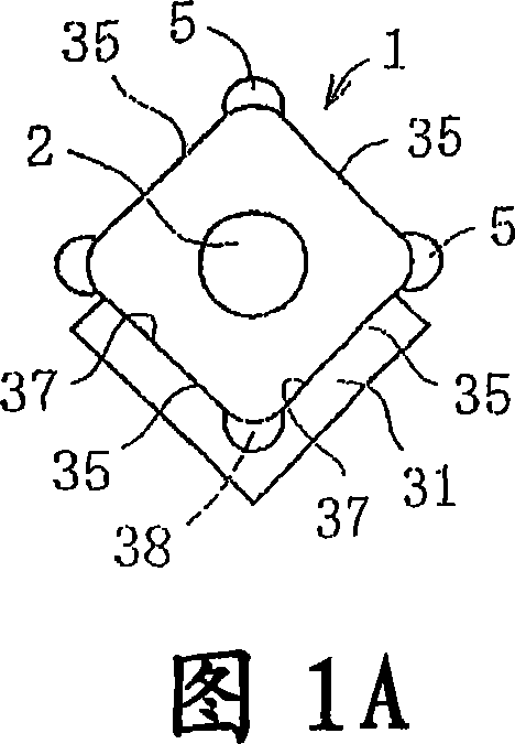
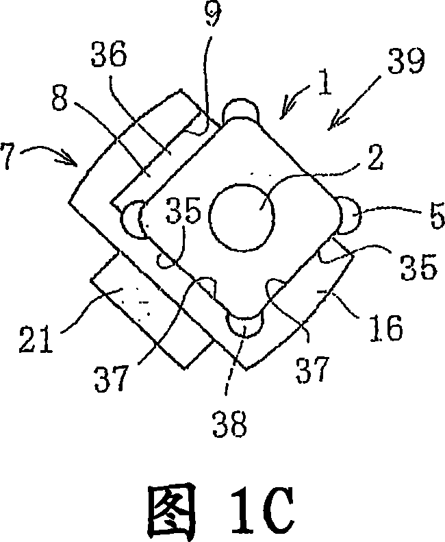
[0037] The feeding device of the projection welding nut of the present invention is a feeding device that has improved the structure of attracting and holding the projection welding nut 1 at the front end of the feed rod 6, and other structures are the same as those shown in FIGS. 2 to 5 described above. devices are the same. Therefore, hereinafter, the shape of the protruding piece 31 constituting a part of the surrounding wall 7 will be described with reference to FIGS. 1A to 1E , and for other configurations, the already described matters will be referred to in conjunction with FIGS. 2 to 5 .

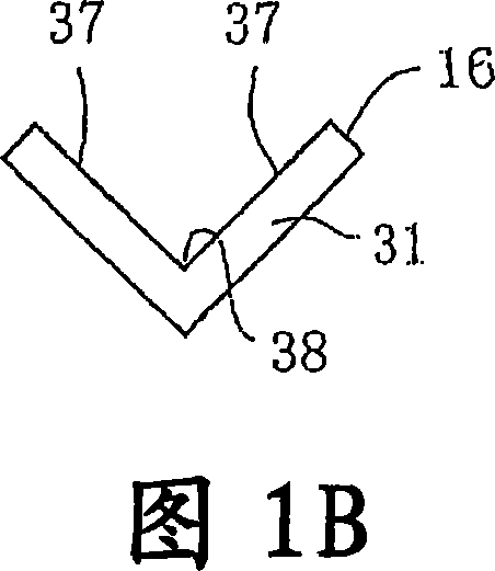
[0038]FIG. 1A is equivalent to the view in the direction of arrow a in FIG. 2 , and FIG. 1B only shows the tab 31 in FIG. 1A . The protruding piece 31 here is made by bending the steel plate to approximately 90 degrees, and an intersecting support surface 37 is formed on the inner side of the protruding piece 31 for supporting the adjacent outer surface 35 of the nut 1 . In addition...


PUM


Abstract

A projection nut feeder capable of accurately aligning the screw hole of a projection nut with an electrode guide pin. A projected piece (31) holding the square projection nut (1) in a fitted state to the outer side face (35) of the nut (1) from the lower side is formed at the tip part of a feed rod (6). Crossing support surfaces (37) supporting the outer surface (35) of the nut (1) are formed on the inside of the projected piece (31). A corner line (38) where both support surfaces (37) cross each other is disposed in the lower direction of the feed rod (6).

Description

technical field [0001] The present invention relates to an apparatus for feeding a projection nut to a guide pin of a fixed electrode. Background technique [0002] Conventional techniques will be described with reference to FIGS. 2 to 5 . 3A and 3B show the situation of feeding the projection welding nut 1 to the guide pin 3 under normal conditions. What the projection welding nut 1 under this traditional technology took is the form that the upper end of the screw hole 2 is installed with a cover 4 . The effect of this kind cover 4 is, when projection welding nut 1 is welded on the lower surface of automobile base plate, be used for preventing the paint that is coated on this lower surface from the sound insulation coating from entering in screw hole 2. In addition, reference numeral 5 denotes a protrusion for welding. [0003] The feed rod 6 is of forward and backward type, and the surrounding wall 7 of the projection welding nut 1 is provided at its front end (it can b...

Claims


Application Information

Patent Timeline
Patent Type & Authority Applications(China)
IPC IPC(8): B23K11/14B23P19/00
CPCB23K11/14B23P19/006B23P19/00
Inventor 青山好高青山省司
Owner 青山好高
Why Eureka
Try Eureka