Imaging lens
a technology of imaging and lens, applied in the field of imaging lenses, can solve the problems of difficult correction of aberrations at the peripheral area, inability to obtain excellent optical performance, etc., and achieve the effects of low profile, high resolution and low f-number
- Summary
- Abstract
- Description
- Claims
- Application Information
AI Technical Summary
Benefits of technology
Problems solved by technology
Method used
Image


Examples
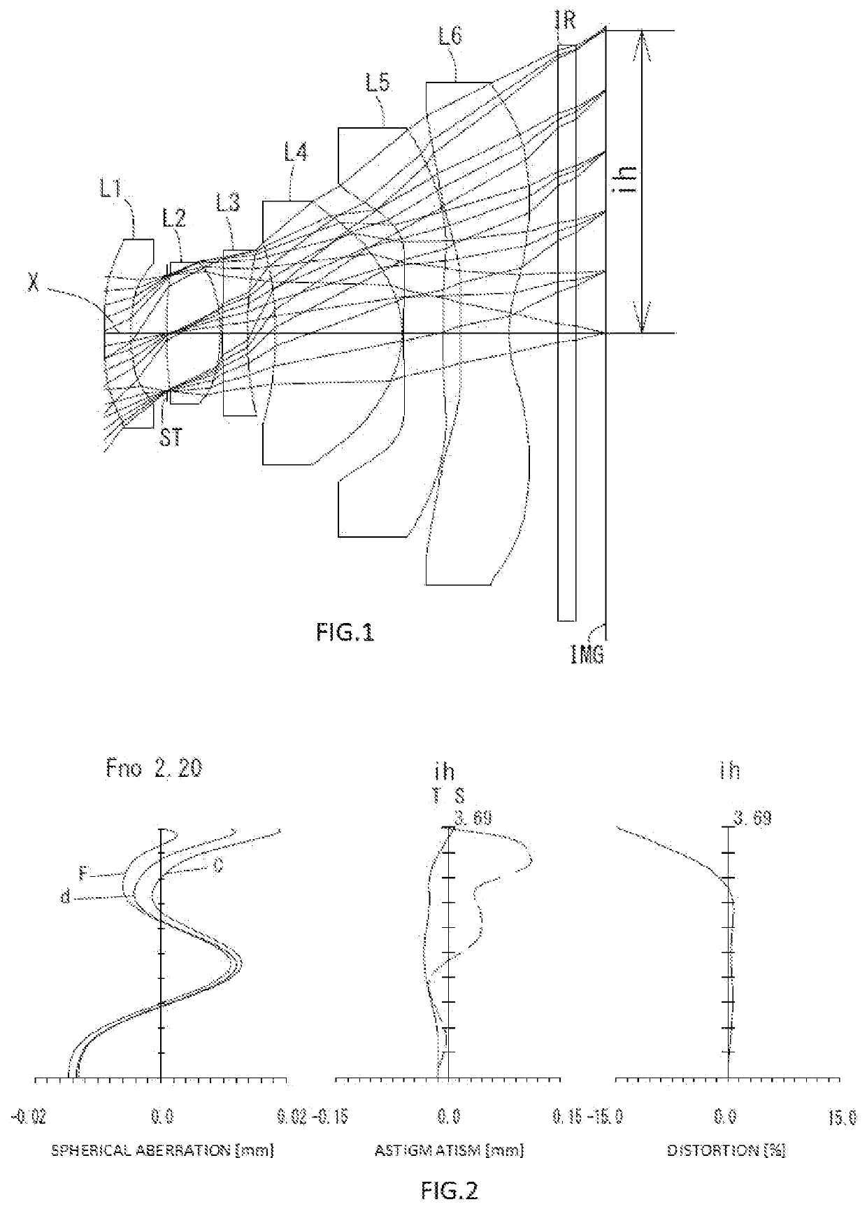
example 1
[0185]The basic lens data is shown below in Table 1.
TABLE 1Example 1Unit mmf = 3.12Fno = 2.20ω(°) = 54.2h = 3.69TTL = 6.03Surface DatairdNdνd(Object)InfinityInfinity 1*10.23530.32751.53555.69(νd1) 2*3.64730.4406 3 (Stop)Infinity−0.0159 4*5.31420.65821.54456.44(νd2) 5*−2.01540.0250 6*7.94020.30001.67119.24(νd3) 7*4.20630.3461 8*−3.90911.53991.53555.69(νd4) 9*−1.11290.020010*Infinity0.48001.67119.24(νd5)11*Infinity0.207412*52.80290.59501.63923.52(νd6)13*1.40840.600014Infinity0.21001.51764.2015Infinity0.3660ImageInfinityPlaneConstituent Lens DataLensStart SurfaceFocal Length11−10.782242.77236−13.780482.441510Infinity612−2.274Aspheric Surface DataFirstSecondFourthFifthSixthSeventhSurfaceSurfaceSurfaceSurfaceSurfaceSurfacek0.000000E+000.000000E+000.000000E+00 3.352432E+00 0.000000E+00 0.000000E+00A42.325862E−013.623732E−014.255530E−02 2.727508E−02−4.321598E−02−2.631253E−02A6−2.513251E−01 4.834690E−011.685821E−01−8.085160E−02−2.004599E−01−8.695072E−02A85.574211E−01−6.726708E+00 −2.420891E...
example 2
[0188]The basic lens data is shown below in Table 2.
TABLE 2Example 2Unit mmf = 3.12Fno = 2.20ω(°) = 53.9h = 3.69TTL = 6.03Surface DatairdNdνd(Object)InfinityInfinity 1*7.85100.32751.53555.69(νd1) 2*3.20180.4457 3 (Stop)Infinity−0.0087 4*6.37180.62501.54456.44(νd2) 5*−1.80160.0250 6*7.19800.30001.67119.24(νd3) 7*3.66260.3576 8*−3.87091.54001.53555.69(νd4) 9*−1.11600.020010*Infinity0.48501.67119.24(νd5)11*Infinity0.222712*Infinity0.59501.63923.52(νd6)13*1.46220.600014Infinity0.21001.51764.2015Infinity0.3549ImageInfinityPlaneConstituent Lens DataLensStart SurfaceFocal Length11−10.364242.65136−11.510482.454510Infinity612−2.288Aspheric Surface DataFirstSecondFourthFifthSixthSeventhSurfaceSurfaceSurfaceSurfaceSurfaceSurfacek0.000000E+000.000000E+000.000000E+00 2.473573E+00 0.000000E+00 0.000000E+00A42.109559E−014.153751E−013.074407E−02 4.041213E−02−3.722932E−02−5.008506E−03A6−9.996069E−02 −5.307388E−01 1.738292E−01−9.343469E−02−1.692019E−01−2.926844E−01A83.197735E−023.999971E+00−2.426969E...
example 3
[0191]The basic lens data is shown below in Table 3.
TABLE 3Example 3Unit mmf = 3.12Fno = 2.20ω(°) = 50.0h = 3.71TTL = 6.03Surface DatairdNdνd(Object)InfinityInfinity 1*5.32140.32781.54456.44(νd1) 2*3.03070.2553 3 (Stop)Infinity0.0554 4*32.64500.65921.54456.44(νd2) 5*−1.61700.0250 6*6.07840.35701.67119.24(νd3) 7*3.16070.5049 8*−3.84641.52101.53555.69(νd4) 9*−0.96350.020010*Infinity0.43001.67119.24(νd5)11*Infinity0.025012*9.84720.60001.63923.52(νd6)13*1.15900.600014Infinity0.21001.51764.2015Infinity0.5095ImageInfinityPlaneConstituent Lens DataLensStart SurfaceFocal Length11−13.618242.84936−10.324482.030510Infinity612−2.112Aspheric Surface DataFirstSecondFourthFifthSixthSeventhSurfaceSurfaceSurfaceSurfaceSurfaceSurfacek0.000000E+000.000000E+00 0.000000E+00 1.746410E+00 0.000000E+00 0.000000E+00A41.334792E−013.058968E−01−1.892492E−02 5.182789E−02−3.306989E−02−3.992342E−02A62.295601E−02−6.711145E−01 7.501182E−01−1.152750E−01−3.382294E−01−1.527517E−01A8−1.410818E−01 1.164009E+01−6.402318...
PUM
 Abstract
Description
Claims
Application Information