
Mechanical high speed roll change system for use with robotic roll change system

a high-speed, mechanical technology, applied in the direction of metal rolling arrangements, cantilevered roll stands, manufacturing tools, etc., can solve the problems of complicated process, increased mass of high-pressure hydraulic tools used to mount and dismount rolls, and heavy rolls with sleeves

Active Publication Date: 2021-09-09
PRIMETALS TECH USA
View PDF0 Cites 0 Cited by
  • Summary
  • Abstract
  • Description
  • Claims
  • Application Information

AI Technical Summary

Benefits of technology

The roll mounting system described in this patent allows for easy positioning and mounting of rolls using a tapered assembly and torque produced by a torque assembly. This results in a more efficient and effective mounting process.

Problems solved by technology

Rolls with sleeves can be as heavy as about 31 kg and the high-pressure hydraulic tools used to mount and dismount the rolls are more massive in some cases.
The weights can exceed the allowable lifting limits and must be mounted from cranes and or manipulators, which further complicate the process of changing a roll.
There is, of course, the risk of injury from trapping hazards and burns from hot equipment while changing the rolls on the machines.

Method used


Image

  • Mechanical high speed roll change system for use with robotic roll change system
  • Mechanical high speed roll change system for use with robotic roll change system
  • Mechanical high speed roll change system for use with robotic roll change system

Examples


Embodiment Construction

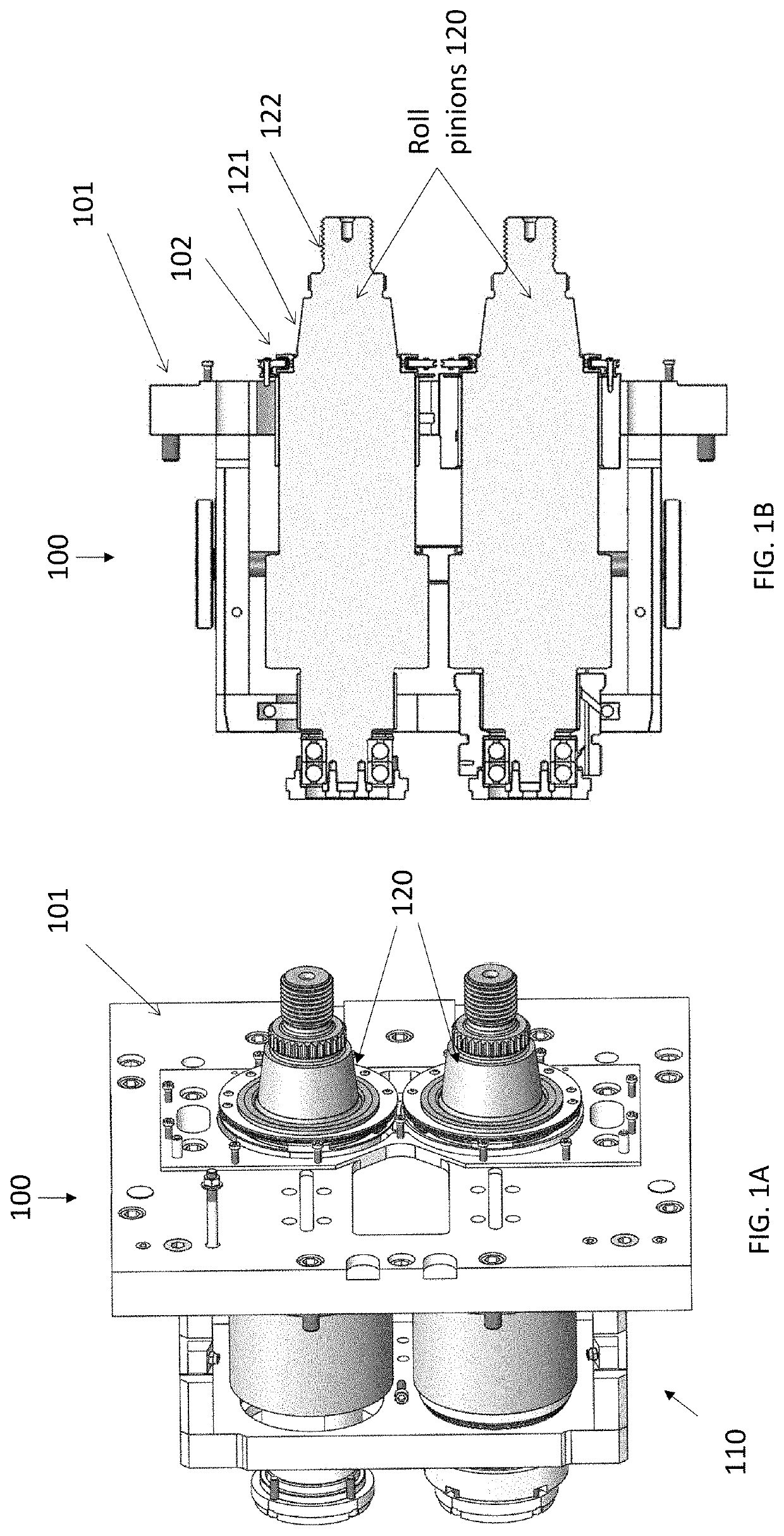
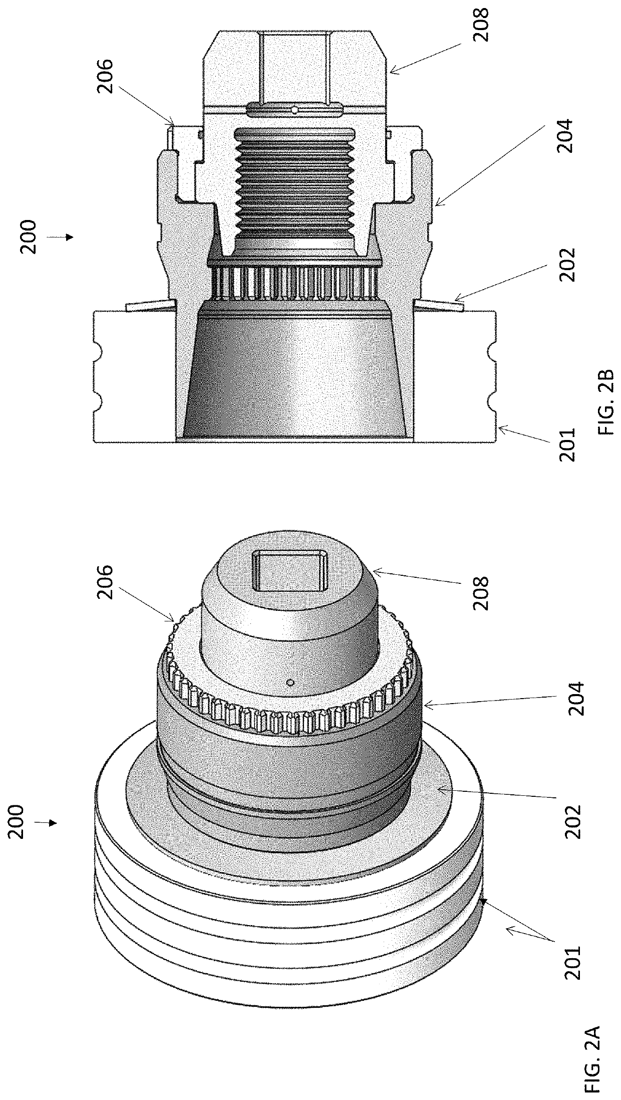
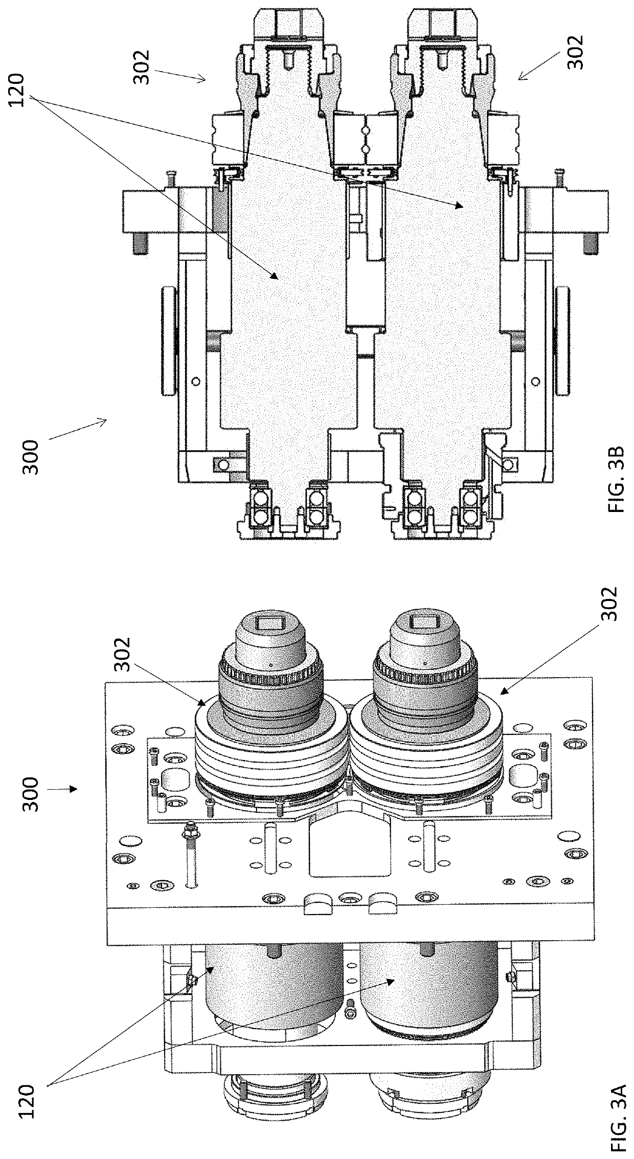
[0014]The disclosure describes a mechanical roll change system for use with robotic or otherwise assisted roll change system. The disclosure solves the problem associated with mechanically changing rolls on cantilevered rolling mill stands. The use of high pressure hydraulics is eliminated, which reduces the weight and complexity of the tooling system. Moreover, multiple tools, (i.e. roll handling, roll mounting and roll removal tools) are not required in some embodiments. With the capability of a new roll mounting and dismounting system to be integrated as an end effector to commercially available manipulators or 6 axis robots, manual removal and mounting of rolls is thus no longer required. Roll change can now be achieved automatically. In some embodiments, the novel roll mounting arrangement eliminates problems with part failures and increases the load-carrying capacity of the rolling mill stand.

[0015]The roll mounting system includes a roll, a spring, a tapered sleeve, a tapered...


PUM

PropertyMeasurementUnit
tapered angleaaaaaaaaaa
timeaaaaaaaaaa

Abstract

A roll mounting system is provided that includes a roll assembly coupled to one or more rolls. The roll assembly is configured to position the one or more rolls using a tapered assembly for mounting or dismounting of the one or more rolls. Also, the roll mounting system includes a torque assembly coupled to the roll assembly. The torque assembly is configured to provide torque to the roll assembly for mounting or dismounting of the one more rolls.

Description

BACKGROUND OF THE INVENTION[0001]The invention relates to the field of wire rod rolling with cantilevered rolling stands Rolls are currently changed manually by operators, for either quality-related issues or when the mill needs to change rolls due to roll wear or to produce another product size. The average change time per stand manually is in the region of 20 min; the most experienced operators can change a stand in 12 min. Rolls with sleeves can be as heavy as about 31 kg and the high-pressure hydraulic tools used to mount and dismount the rolls are more massive in some cases. The weights can exceed the allowable lifting limits and must be mounted from cranes and or manipulators, which further complicate the process of changing a roll. There is, of course, the risk of injury from trapping hazards and burns from hot equipment while changing the rolls on the machines.SUMMARY OF THE INVENTION[0002]According to one aspect of the invention, there is provided a roll mounting system. Th...

Claims


Application Information

Patent Timeline
Patent Type & Authority Applications(United States)
IPC IPC(8): B21B31/10B21B1/16
CPCB21B31/10B21B1/16B21B31/08B21B31/103B21B13/005B21B27/035
Inventor SHEN, WILLIAMPALFREMAN, MATTHEW
Owner PRIMETALS TECH USA
Learn More