Plantar pressure sensing system

a technology of sensing system and pressure reading, which is applied in the field of sensing system, can solve the problems of inability to popularize, increase the cost of such products, and the inability to meet the needs of aforementioned products, so as to improve the data validity of the system and more accurate pressure readings

Active Publication Date: 2021-10-07
CHANG GUNG UNIVERSITY
View PDF7 Cites 0 Cited by
  • Summary
  • Abstract
  • Description
  • Claims
  • Application Information

AI Technical Summary

Benefits of technology

[0004]In order to solve the abovementioned problems, some embodiments of the present invention provide a sensing system, in particular a sensing system for foot pressure sensing, taking advantage of being able to calculate the pressure of the sole accurately and in real time. Specifically, it utilizes the alignment setting of the convex portions to assist the sensors in pressure detection, therefore more accurate pressure readings can be obtained. As a result, the data validity of the system is improved.

Problems solved by technology

However, based on cost considerations, there is only a single sensor set at the heel position in most of the relevant products currently on the market.
Therefore, when the user requires more complete correction or detected information (such as assisting people with physical disabilities to perform gait training), the aforementioned products don't exactly meet the needs and remains to be improved.
In addition, while a small number of products set the sensor according to the needs of users, they cannot be popularized because there is no related configuration logic (that is, the operating specifications).
Among them, products that can be popularized are usually achieved by using sensors on the soles of the shoes, but the cost of such products is more expensive, and it is not affordable for general users.

Method used


Image

  • Plantar pressure sensing system
  • Plantar pressure sensing system

Examples


Embodiment Construction

[0010]To clarify the purpose, technical solutions, and the advantages of the disclosure, embodiments of the present disclosure will now be described more fully hereinafter with reference to the accompanying drawings.

[0011]The present invention relates to a kind of sensing system, especially a sensing system to detect the plantar pressure.

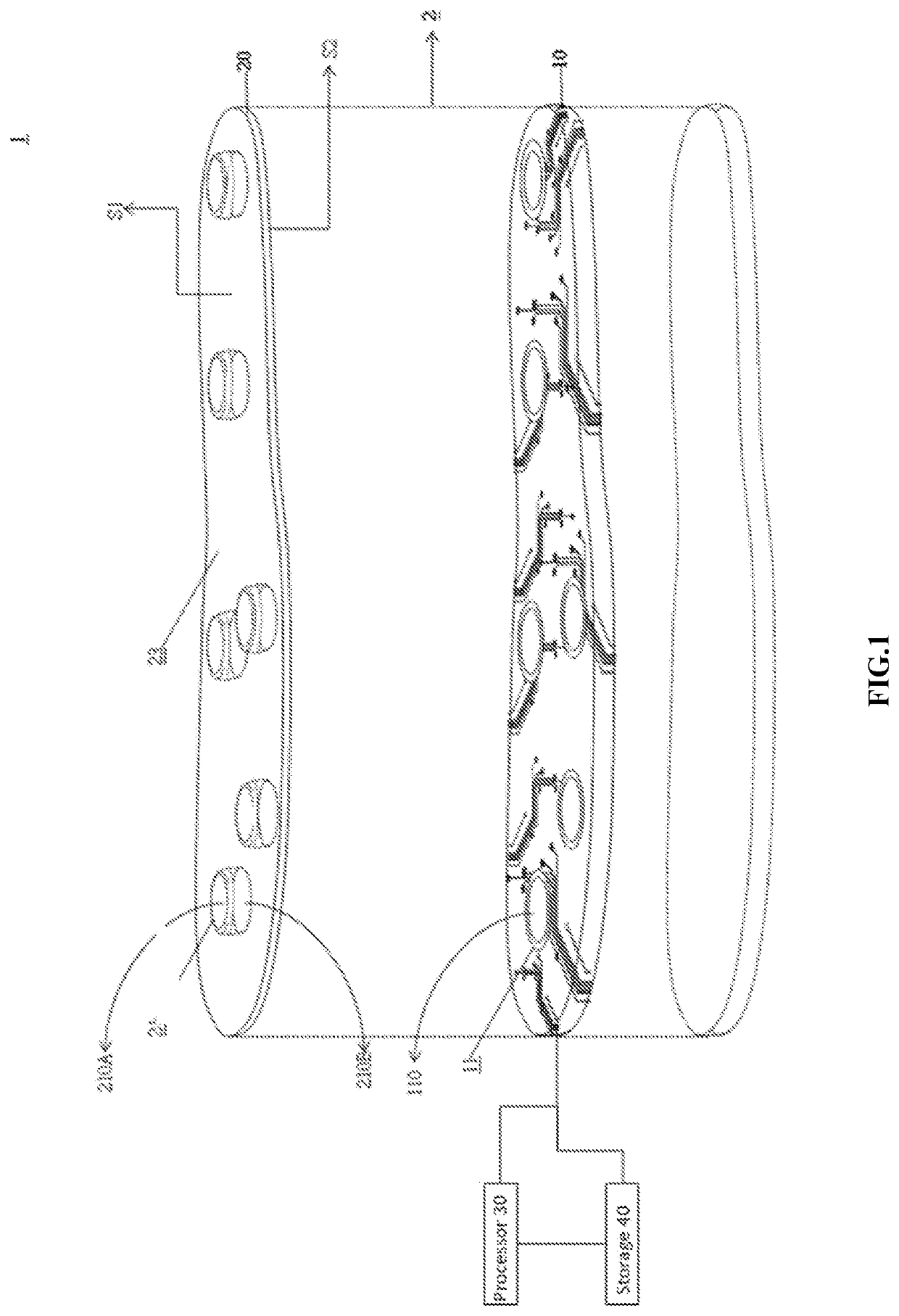
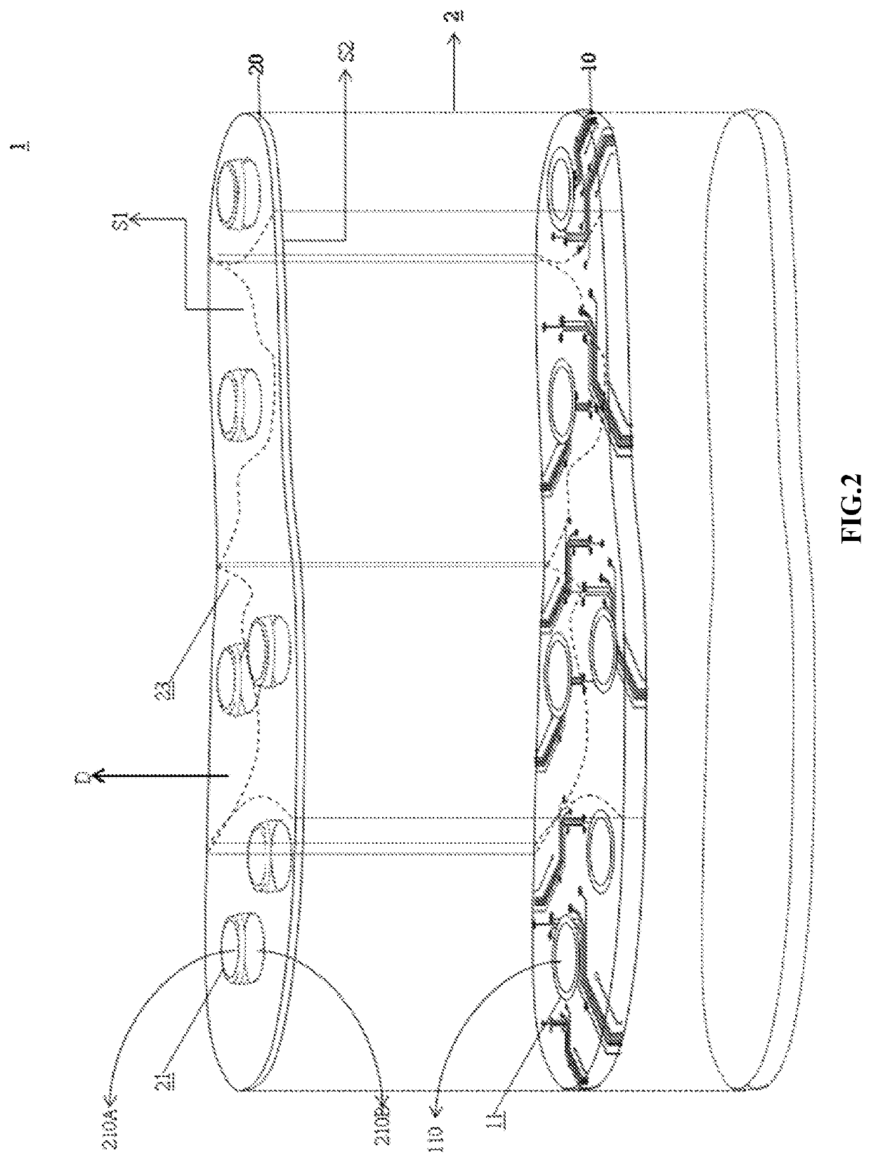
[0012]Please refer to FIG. 1. FIG. 1 is a schematic diagram of some embodiments of the foot pressure sensing system of the present invention. The foot pressure sensing system 1 of this embodiment is disposed on a sole 2 and includes a plurality of sensors 11, a plurality of convex portions 21, a plurality of connecting portions 23, at least one processor 30 and at least one storage 40. The processor 30 is connected to the storage 40 and configured to connect to the sensors 11. The sensors 11 are configured to form at least one first layer 10 of the sole 2, and the convex portions 21 and the connecting portions 23 are configured to form the at least ...


PUM

PropertyMeasurementUnit
pressureaaaaaaaaaa
shapeaaaaaaaaaa
areasaaaaaaaaaa

Abstract

A plantar pressure sensing system is located at a sole of shoe. The plantar pressure sensing system comprises at least a first layer and at least a second layer. Furthermore, the plantar pressure sensing system includes: a plurality of sensor, a plurality of convex portions, a plurality of connection portions, at least a processor and at least a storage. The processor is coupled with the storage and configured to be connected with the plurality of sensors. The plurality of sensors are configured to form the first layer. The plurality of convex portions and the plurality of connection portions are configured to form the second layer. Overall, the plantar pressure sensing system is able to detect pressure with the sensors by setting the alignment of the convex portions, thereby obtaining a more accurate pressure(s) reading from the sole of shoe. The data validity of the plantar pressure sensing system is improved.

Description

TECHNICAL FIELD[0001]The present invention relates to a kind of sensing system, especially a sensing system to detect the plantar pressure.DESCRIPTION OF THE RELATED ART[0002]In recent years, with the increasing popularity of auxiliary gait performance correction devices, it is more and more common to install sensors inside (or at the bottom) of shoes. Usually, the sensor detects the pressure value of the human foot to enhance gait function and activities or improve the collection of detected information. Generally speaking, the accuracy of the gait performance test is related to the number of sensors; that is, the more sensors there are, the easier it is to obtain information close to the exact gait performance. However, based on cost considerations, there is only a single sensor set at the heel position in most of the relevant products currently on the market. Therefore, when the user requires more complete correction or detected information (such as assisting people with physical...

Claims


Application Information

Patent Timeline
Patent Type & Authority Applications(United States)
IPC IPC(8): A61B5/103G01L5/00A61B5/00
CPCA61B5/1038G01L5/0052A61B2562/046A61B2562/0247A61B5/6807G01L1/205
Inventor CHAN, HSIAO-LUNGLIAW, JIUNN-WOEICHANG, YA-JUKUO, CHENG-CHUNG
Owner CHANG GUNG UNIVERSITY
Why Eureka
Try Eureka