External mount differential tire pressure sensor system

a technology of differential tire pressure sensor and external mount, which is applied in vehicle tyre testing, vehicles, instruments, etc., can solve the problems of increasing the manufacturing cost of the entire automobile, affecting the accuracy of tire pressure readings, and complex system components within the tire casing. , to achieve the effect of reducing or eliminating inaccurate pressure readings, simple and inexpensive manufacturing and installation, and easy and inexpensive replacemen

Inactive Publication Date: 2005-03-29
SILICON VALLEY MICRO C
View PDF1 Cites 2 Cited by
  • Summary
  • Abstract
  • Description
  • Claims
  • Application Information

AI Technical Summary

Benefits of technology

The invention comprises a method and system for monitoring internal vehicle tire pressure employing externally-mounted components which are relatively simple and inexpensive to manufacture and install on a vehicle, which provide accurate internal tire pressure readings, which can easily and inexpensively be replaced in case of failure, and which substantially reduce or entirely eliminate inaccurate pressure readings due to the effect of centrifugal forces on the sensor components.

Problems solved by technology

Firstly, the installation of the system components within the tire casing is not simple, requires careful attention to the component location and mounting, and increases the manufacturing cost of the entire automobile.
In addition, many vehicles use steel-belted tires, which interact in a detrimental manner with the r.f. signals generated internally of the tire.
Further, when the battery or one of the other system components fails, replacement of the defective component requires that the affected tire be removed from the wheel before replacement can be done, which is costly and time consuming.
While this design arrangement avoids the disadvantages noted above associated with internally mounted tire pressure monitoring systems, the accuracy of such external mount sensors is adversely affected by the centrifugal forces associated with the rotating wheel.
In particular, as the angular velocity of the wheel changes, the centrifugal force acting on the slider element within the sensor also changes, causing additional force to act on the slider.
As a result, the sensor can easily produce false warning signals, and can also fail to generate a valid warning signal.
This problem is compounded by the fact that the sensor guide may not be mounted exactly radially of the wheel, but at an angle with respect to the radial direction.
Consequently, it is difficult to design a sensor in such a manner as to compensate for the centrifugal force component acting on the sensor slider.
Efforts to provide a simple yet accurate and durable tire pressure monitoring system using an external valve stem mounting configuration have not been successful to date.

Method used


Image

  • External mount differential tire pressure sensor system
  • External mount differential tire pressure sensor system
  • External mount differential tire pressure sensor system

Examples


Embodiment Construction

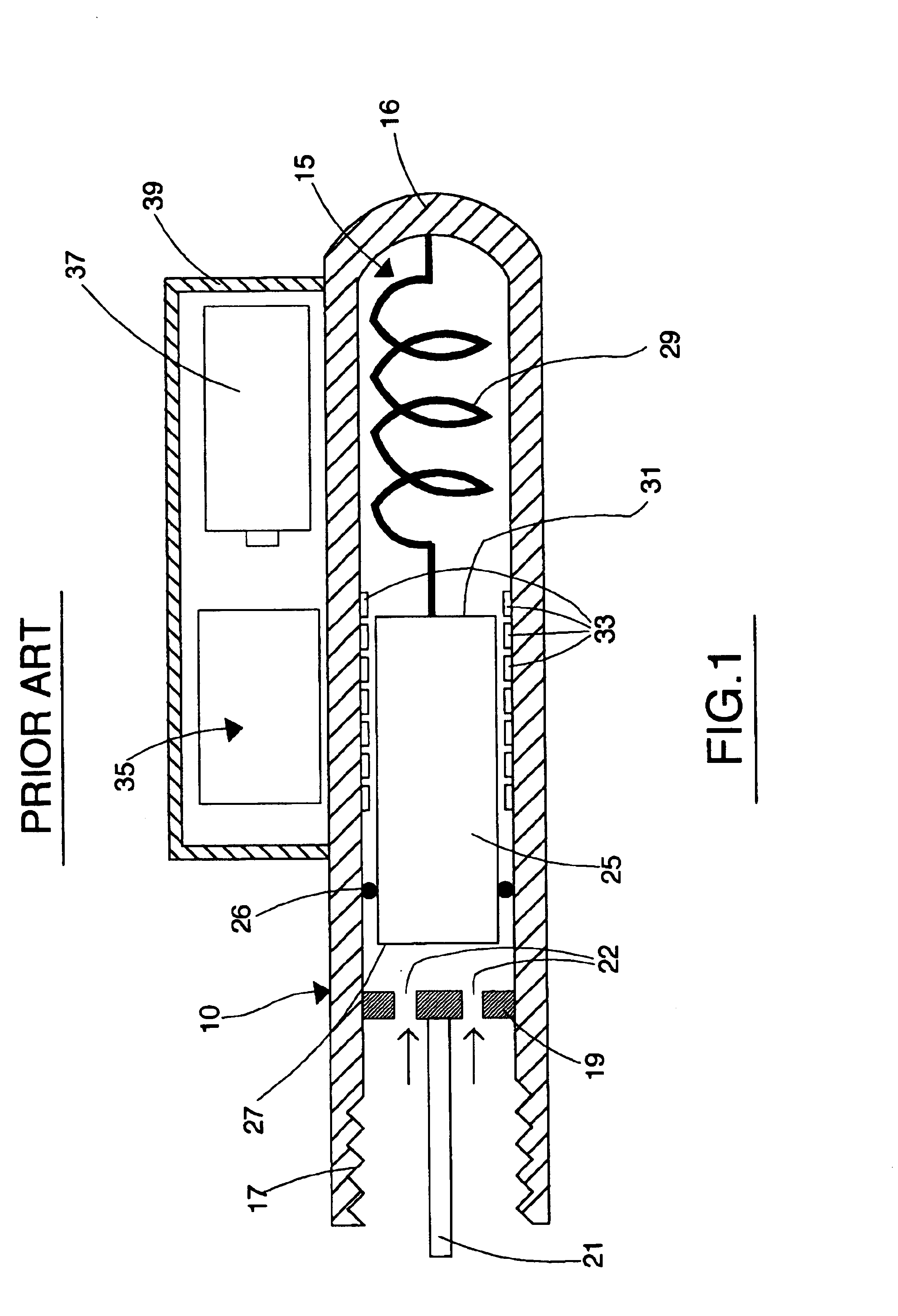
Turning now to the drawings, FIG. 1 is a schematic sectional view of a typical prior art external valve stem mounted tire pressure sensor. As seen in this Fig., the known tire pressure sensor system includes an electromechanical sensor generally designated with reference numeral 10 having a main guide body member 12 fabricated from a durable metal, such as steel, aluminum, or the like. Guide body member 12 has a longitudinally extending central bore 15 which is closed at one end by an integral end wall portion 16. The other end of guide body member 12 is open and the internal wall portion of this open end is provided with internal threads 17 of size and pitch to sealingly engage the external threads of a conventional tire valve stem (not shown). A bore partition 19 is arranged within bore 15 adjacent the open end, and includes a centrally positioned outwardly extending plunger 21 which engages the tire valve stem plunger when the sensor is threadedly attached to the tire valve stem ...


PUM

PropertyMeasurementUnit
arcuate shapeaaaaaaaaaa
flexibleaaaaaaaaaa
pressureaaaaaaaaaa

Abstract

An external mount tire pressure sensor system which substantially reduces the effect of centrifugal force on tire pressure measurements. A sensor has a main guide body portion with two parallel leg portions each having a central bore. A slider element is slidably mounted in each leg portion, and the two slider elements are mechanically connected for translatory movement in unison. A spring urges the slider elements to a neutral position. The sensor attaches to a tire valve stem. Gas from a tire encounters one of the slider elements and urges it in opposition to the spring force. The differential interconnection between the two slider elements cancels out the effect of the centrifugal force when the wheel rotates. A stiff flexible wall section enables the axis of the sensor to be aligned with the wheel radius to optimize performance.

Description

BACKGROUND OF THE INVENTIONThis invention relates to automotive tire pressure sensors. More particularly, this invention relates to a method and system for monitoring internal tire pressure of vehicles using an externally mounted sensor.Tire pressure sensor systems are known and are commonly used to monitor the internal air pressure in individual pneumatic tires of a vehicle and to provide a warning signal to the driver whenever the internal air pressure in one or more of the vehicle tires is dangerously low or high. The warning signal is typically generated by an r.f. signal generator controlled by a microprocessor connected to the tire pressure sensor whenever the internal tire pressure measured by the sensor lies outside a predetermined normal operating range. This r.f. signal is transmitted to a vehicle-mounted receiver, which uses the warning signal to alert the driver either visually (by activating a warning lamp or display) or audibly (by activating an audible alarm) or both....

Claims


Application Information

Patent Timeline
Patent Type & Authority Patents(United States)
IPC IPC(8): B60C23/04B60C23/02G01L19/00G01L19/02
CPCG01L19/02B60C23/0408
Inventor HUANG, SU SHIONG
Owner SILICON VALLEY MICRO C
Why Eureka
Try Eureka