

Pivotable Bolt
a pivoting bolt and latch technology, applied in the field of pivoting bolts, can solve the problems of limiting the size of a deadbolt or latch, the overall size of a door lock intended for human handling, and the general failure of approaches, so as to improve the resistance to forceful impacts.
- Summary
- Abstract
- Description
- Claims
- Application Information
AI Technical Summary
Benefits of technology
Problems solved by technology
Method used
Image

Examples
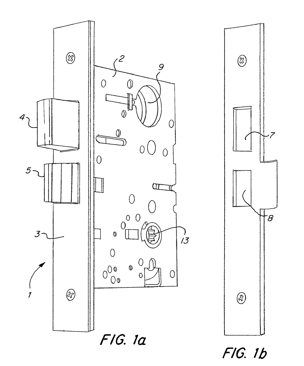
first embodiment
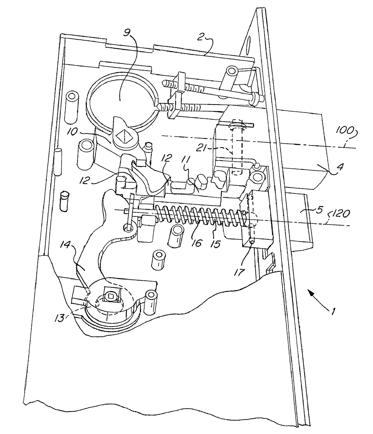
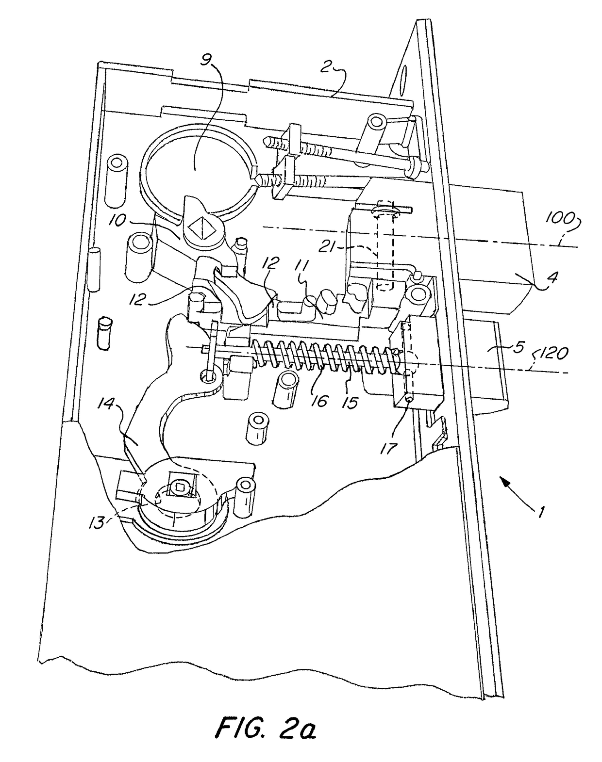
[0046]FIGS. 3, 4a, and 4b show additional details of a deadbolt assembly 20 according to the present invention. The tailpiece 11 includes a pin 21, which, in the embodiment shown, is in the form of a cylindrical rod. In this embodiment, the pin 21 is integral with the rest of the tailpiece 11. The tailpiece 11 is formed by any suitable metal forming process, including casting, forging, etc. The deadbolt 4 includes a hole 22 adapted to receive the pin 21. In the embodiment shown, the hole is cylindrical in shape.
[0047]The pin 21, in this embodiment, includes a notch 24 that is adapted to receive a clip 25. The clip 25 is used to retain the pin 21 in the hole 22 formed in the deadbolt 4. To accommodate the clip 25, the deadbolt 4 has a slot 23. Once the tailpiece 11 has been attached to the deadbolt 4 by insertion of the pin 21 into the hole 22, the clip 25 is snapped into place on the notch 24. The clip 25 fits within the slot 23 and prevents the pin 21 from being removed from the ho...
third embodiment
[0052]FIGS. 6a, 6b, and 6c show a deadbolt assembly according to the present invention. In this embodiment, both the deadbolt 64 and the tailpiece 71 have holes 82a and 82b for receiving a pin 81. The pin 81 is, in this embodiment, a separate component from both the deadbolt 64 and the tailpiece 71. In order for this embodiment to function reliably, two retaining clips 55a and 55b are required. The pin 81 has two notches 84a and 84b for receiving the retaining clips. The deadbolt 64 has a slot 83a for accommodating one of the clips and the tailpiece 71 has a slot 83b for accommodating the other of the clips. The slots 83 and clips 84 cooperate to hold the components of the deadbolt assembly shown in FIGS. 6a, 6b, and 6c together. As in the previously described embodiments, the deadbolt 64 and tailpiece 71 will, when assembled pivot relative to one another about the axis 103. When the deadbolt assembly is installed in a mortise lock assembly and installed in a door, the axis 103 is o...
PUM
 Abstract
Description
Claims
Application Information