
Drain pan extension

a technology of drain pan and extension, which is applied in the field of drain pan extension, can solve the problems of moisture damage, typically failed drain pan etc., and achieve the effect of convenient automatic and secure configuration, convenient reconfiguration, and effective capture of liquid condensate blow

Active Publication Date: 2021-12-02
ADVANCED DISTRIBUTOR PRODS
View PDF6 Cites 0 Cited by
  • Summary
  • Abstract
  • Description
  • Claims
  • Application Information

AI Technical Summary

Benefits of technology

Effectively captures liquid condensate that traditional drain pans miss, reducing moisture-related damage and facilitating straightforward installation and adjustment for different HVAC systems and environments without complex maintenance.

Problems solved by technology

However, the drain pan typically fails to capture liquid condensate that is pushed horizontally from the surface of the coil by air flowing through the HVAC system (i.e., air flowing across the evaporator coil).
This liquid condensate that is pushed in a horizontal direction is sometimes referred to as evaporator “blow off” and can result in moisture damage (e.g., corrosion and / or growth of biological contamination such as mold) in both the HVAC system (e.g., the surface of ducts downstream from the evaporator coil) and the surroundings of the horizontal evaporator coil (e.g., the attic floor and / or the underlying portion of the ceiling in a room below the attic).

Method used


Image

  • Drain pan extension
  • Drain pan extension
  • Drain pan extension

Examples


Embodiment Construction

[0018]Embodiments of the present disclosure and its advantages are best understood by referring to the drawings, like numerals being used for like and corresponding parts of the various drawings.

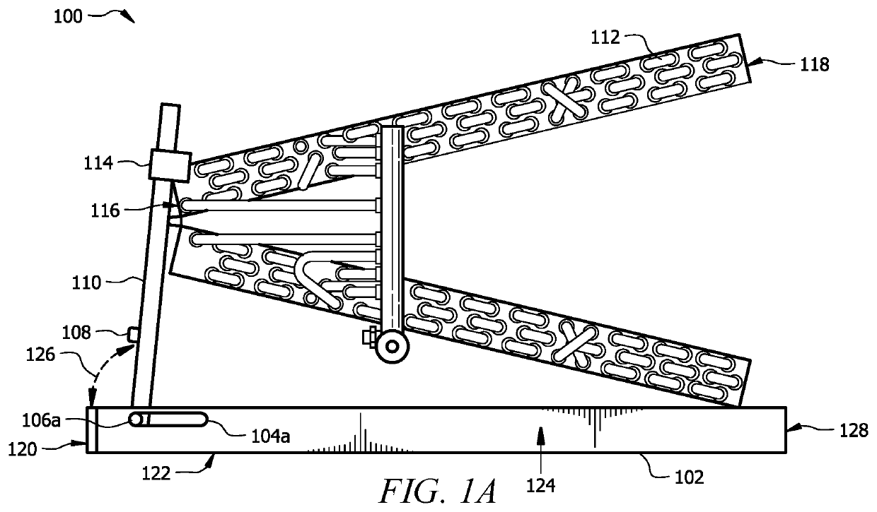
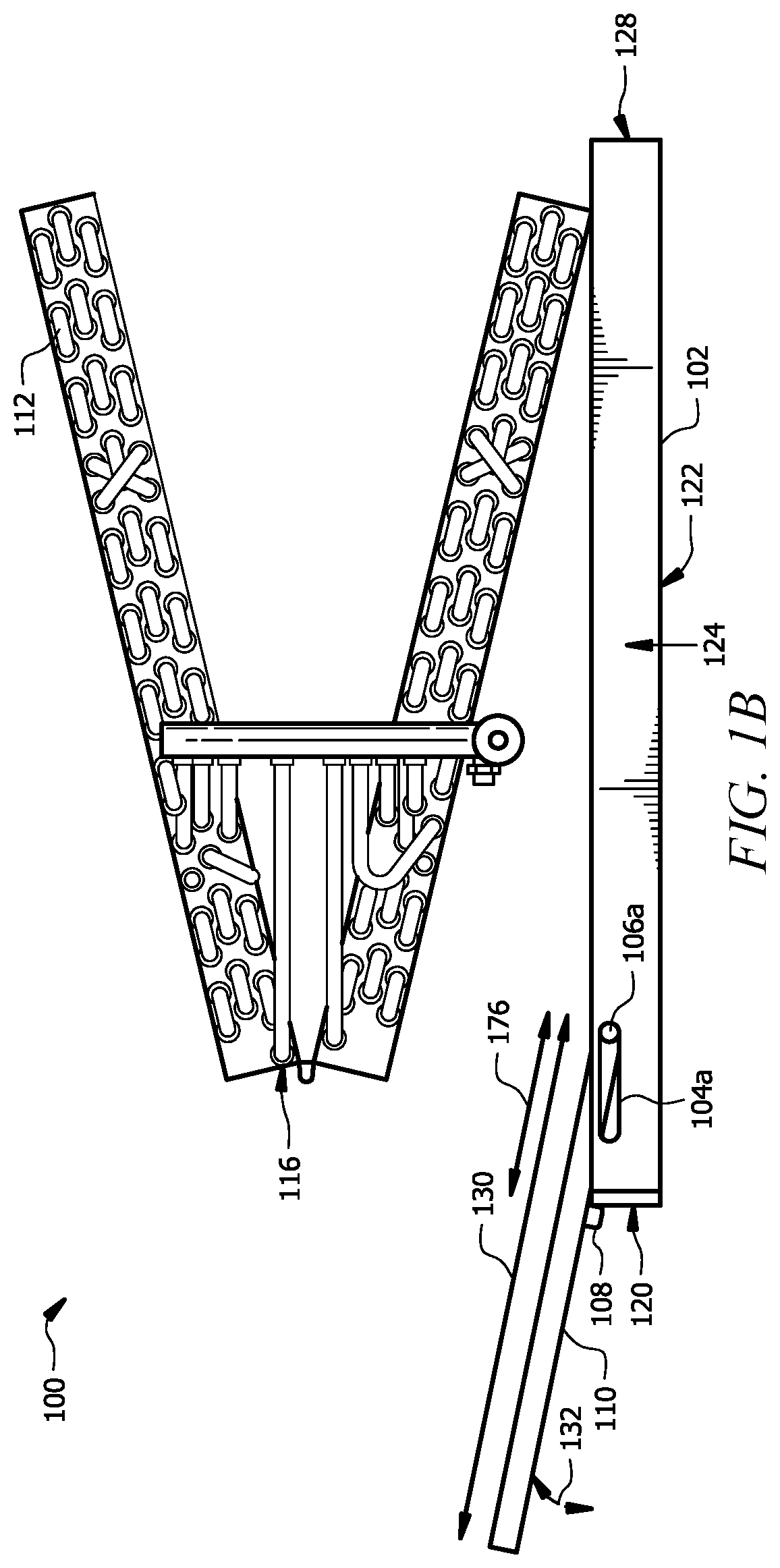
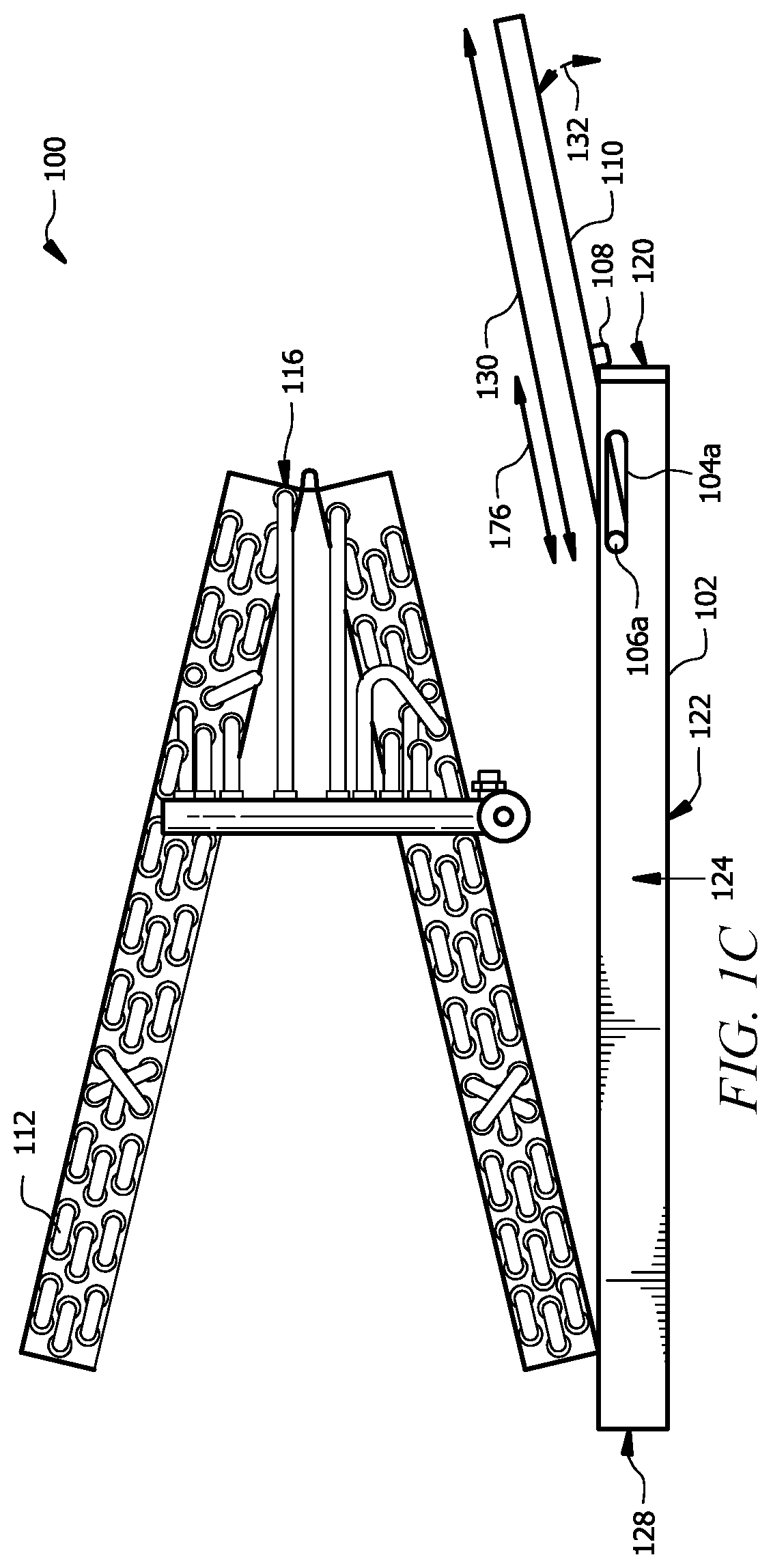
[0019]FIGS. 1A-C and 2A-C show an example apparatus 100 according to the present disclosure. FIGS. 1A and 1B show apparatus 100 in a first configuration (e.g., a transportation configuration) and a second configuration (e.g., an installation configuration), respectively. FIGS. 2A-C show perspective views of the apparatus 100 in the second (e.g., installation) configuration of FIG. 1B.

[0020]Apparatus 100 is generally configured to receive liquid condensate from an evaporator coil 112, as shown in FIGS. 1A and 1B. For example, the apparatus 100 may be placed below the evaporator coil 112 to receive liquid condensate from the coil 112. Apparatus 100 includes a drain pan 102 disposed below the coil 112, and a drain pan extension 110 attached to the drain pan 102. The drain pan 102 has a first no...


PUM


Abstract

An apparatus includes a drain pan configured to receive liquid condensate from a horizontal evaporator coil above the drain pan and a drain pan extension coupled to the drain pan. A pin on the front and rear sides of the drain pan extension is fitted and movable within a corresponding notch in the front and rear sides of the drain pan. The drain pan extension is securably configurable in a first configuration and a second configuration. In the first configuration, the drain pan extension extends above the drain pan at a first angle relative to the drain pan. In the second configuration, at least a portion of the drain pan extension extends beyond the left pan side of the drain pan at a angle, which may be selected for improved capture of liquid condensate from the horizontal evaporator coil.

Description

CROSS-REFERENCE TO RELATED APPLICATIONS[0001]This application is a continuation of U.S. patent application Ser. No. 16 / 427,694 filed May 31, 2019, by John Bauer et al., and entitled “DRAIN PAN EXTENSION,” which is incorporated herein by reference.TECHNICAL FIELD[0002]This disclosure relates generally to heating, ventilation, and air conditioning (HVAC) systems. In particular embodiments, this disclosure relates to a reconfigurable drain pan extension for use with a horizontal evaporator coil.BACKGROUND[0003]Heating, ventilation, and air conditioning (HVAC) systems are used to regulate environmental conditions within an enclosed space. HVAC systems include a horizontal evaporator coil for cooling and / or dehumidifying air and a blower that pulls warm air from the enclosed space and pushes the air across the horizontal evaporator coil before it is returned, as conditioned air, via one or more ducts to the enclosed space. During operation of the horizontal evaporator coil, water vapor f...

Claims


Application Information

Patent Timeline
Patent Type & Authority Applications(United States)
IPC IPC(8): F24F13/22
CPCF24F13/222F24F13/30
Inventor BAUER, JOHNDENLEY, MICHAEL
Owner ADVANCED DISTRIBUTOR PRODS
Learn More