
Moving robot and traveling method thereof in corner areas

a robot and corner area technology, applied in the field of corner area robot and traveling method thereof, can solve the problems of difficult to travel appropriately according, obstacles such as vases and glass cups made of transparent materials in the corner area, and achieve the effect of improving accuracy, stability and reliability of traveling, and enhancing utility and efficiency of 3d camera sensors

Pending Publication Date: 2021-12-02
LG ELECTRONICS INC
View PDF1 Cites 1 Cited by
  • Summary
  • Abstract
  • Description
  • Claims
  • Application Information

AI Technical Summary

Benefits of technology

The present invention is about an improved moving robot that can detect and avoid obstacles in corners with high accuracy. This is achieved by using a 3D camera sensor to generate image information, which is then analyzed to identify obstacles. As a result, the robot can travel safely and efficiently in corner areas, preventing damage or breakdown due to erroneous obstacle detection. Additionally, the use of the 3D camera sensor enhances the usefulness and efficiency of the system.

Problems solved by technology

However, when moving according to a traveling (driving) mode disclosed in the prior literature, it is difficult to detect an obstacle existing in a corner area due to the nature of the obstacle, and thus, there is a limitation in that it is difficult to travel appropriately according to presence or absence of an obstacle.
In particular, there is a high possibility that obstacles such as a desk, a closet, a chest of drawers, and a table where only legs are recognized, or obstacles made of transparent materials such as vases and glass cups exist in the corner area.
These obstacles are difficult to be detected and distinguished.
Since the related art technology detects obstacles using line beams, there is a limitation in that the obstacle detection is incorrectly performed when the shape of an obstacle is difficult to be detected as a line.
For example, in the case of a corner area where two walls meet and a plurality of lines is detected, there is a problem that accurate detection of presence or absence of an obstacle is difficult.
In addition, there is a high possibility that various types of obstacles are disposed in the corner areas, and thus the identification of the obstacles becomes difficult.
If an obstacle is not accurately detected when traveling in the corner area, there is a risk that the robot cleaner collides with the obstacle and thereby the robot cleaner or the obstacle is damaged.
This brings about a problem that the corner area cannot be cleaned smoothly.

Method used


Image

  • Moving robot and traveling method thereof in corner areas
  • Moving robot and traveling method thereof in corner areas
  • Moving robot and traveling method thereof in corner areas

Examples


Embodiment Construction

[0034]Hereinafter, description will be given in detail of implementations disclosed herein. Technical terms used in this specification are merely used for explaining specific implementations, and should not be constructed to limit the scope of the technology disclosed herein.

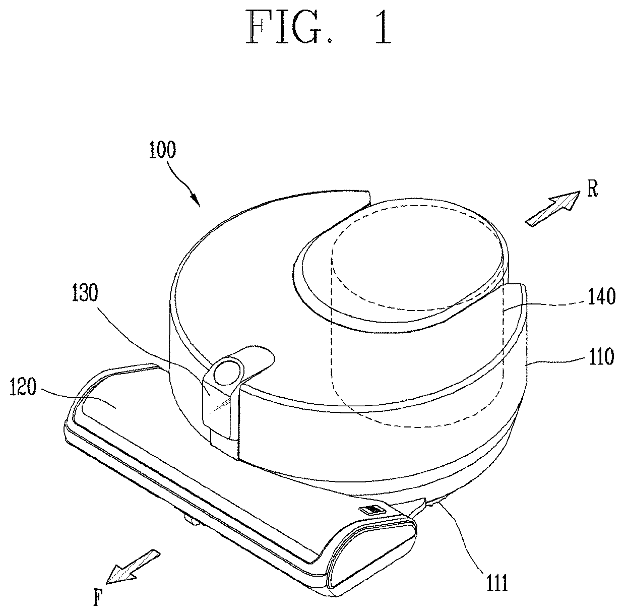
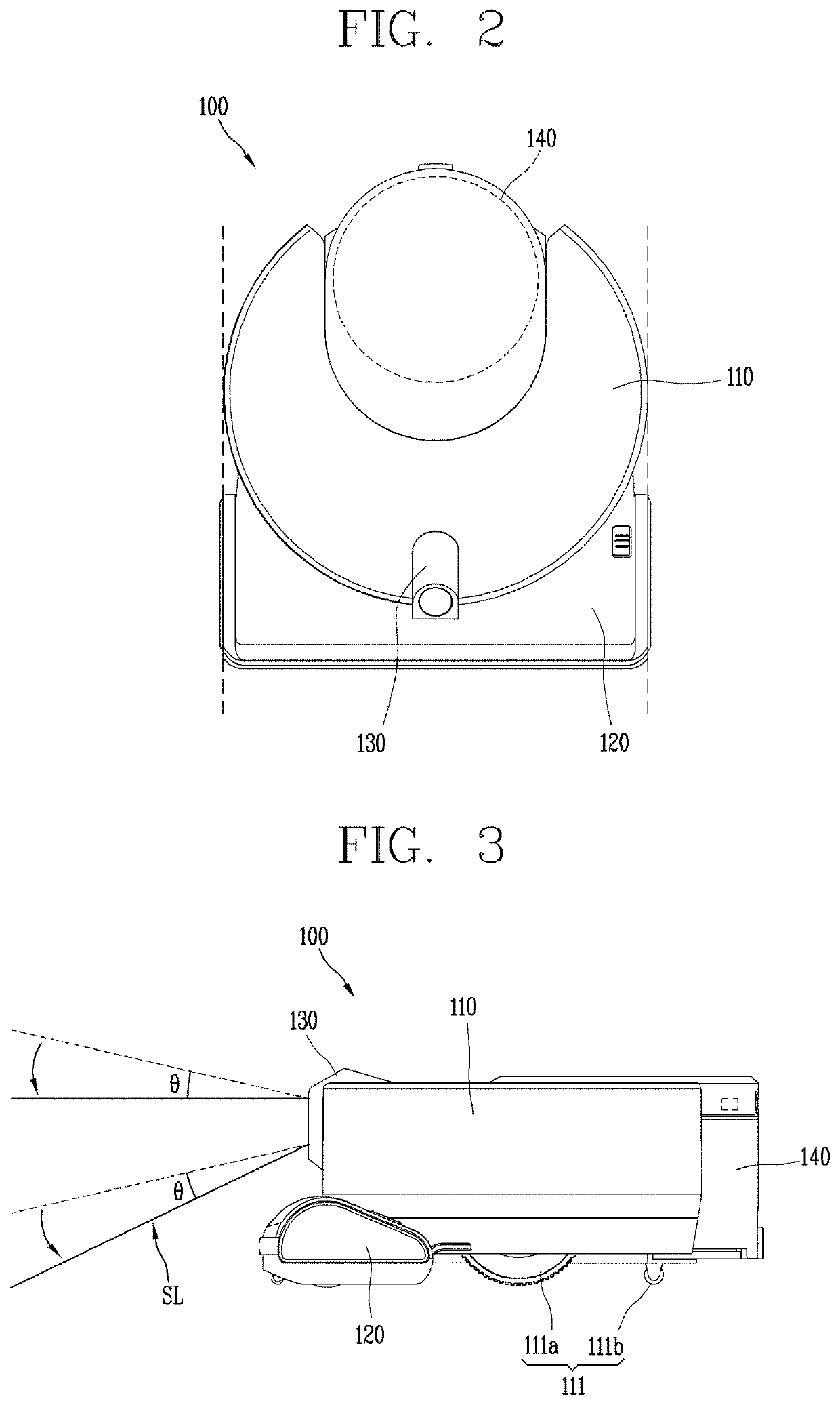
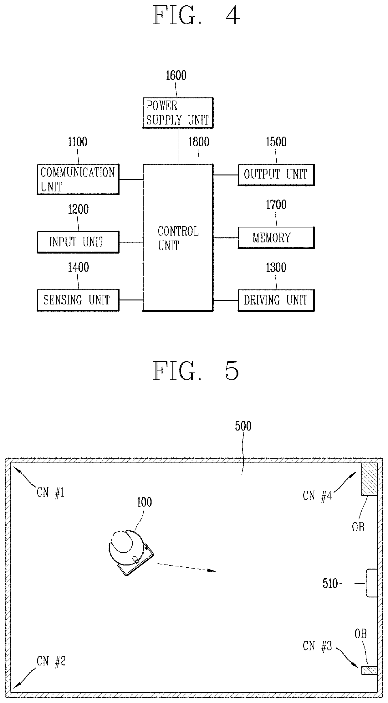
[0035]FIG. 1 is a perspective view illustrating one implementation of a robot cleaner 100, FIG. 2 is a planar view of the robot cleaner 100 illustrated in FIG. 1, and FIG. 3 is a lateral view of the robot cleaner 100 illustrated in FIG. 1.

[0036]For reference, in this specification, a moving robot, a robot cleaner, and a cleaner that performs autonomous traveling may be used in the same sense.

[0037]Referring to FIGS. 1 to 3, a robot cleaner 100 performs a function of cleaning a floor while traveling on a predetermined area by itself. Cleaning the floor disclosed herein includes sucking dust (including foreign materials) on the floor or mopping the floor.

[0038]The robot cleaner 100 includes a cleaner body 110, a s...


PUM


Abstract

The present disclosure relates to a moving robot that generates image information by accumulating results of sensing a corner area using a 3D camera sensor, and detects an obstacle by extracting an area for identifying the obstacle from the image information, and a traveling method thereof in corner areas.

Description

CROSS-REFERENCE TO RELATED APPLICATION[0001]Pursuant to 35 U.S.C. § 119(a), this application claims the benefit of the earlier filing date and the right of priority to Korean Patent Application No. 10-2020-0063230, filed on May 26, 2020, the contents of which is incorporated by reference herein in its entirety.BACKGROUND1. Technical Field[0002]The present disclosure relates to a moving robot traveling while cleaning a traveling area and a traveling method thereof in corner areas.2. Description of the Related Art[0003]In general, robots have been developed for industrial use and have been partially in charge of factory automation. In recent years, the field of applications of robots has been expanded, and home robots that can be used in ordinary homes as well as aerospace robots and medical robots have been made.[0004]A representative example of the home robot is a robot cleaner, which is a type of household appliance that sucks and cleans dust or foreign materials around the robot w...

Claims


Application Information

Patent Timeline
Patent Type & Authority Applications(United States)
IPC IPC(8): G05D1/02H04N5/225H04N13/239G06K9/00H04N13/207G06K9/20G06K9/62
CPCG05D1/0251G05D1/0214H04N5/2256H04N13/239G05D2201/0215H04N13/207G06K9/2054G06K9/6201G06K9/00664G05D1/0219G06V20/10G06V2201/12G01B11/25G01S17/931H04N23/56H04N23/57H04N23/90H04N23/20B25J11/0085B25J9/1664B25J9/1676B25J9/1694B25J19/021A47L9/2852A47L2201/04G06F18/22G05D1/246G05D1/617G05D1/2435
Inventor JOO, JINUHKIM, JUNGSIK
Owner LG ELECTRONICS INC
Learn More