
Common mode filter

Pending Publication Date: 2021-12-16
TDK CORPARATION
View PDF0 Cites 0 Cited by
  • Summary
  • Abstract
  • Description
  • Claims
  • Application Information

AI Technical Summary

Benefits of technology

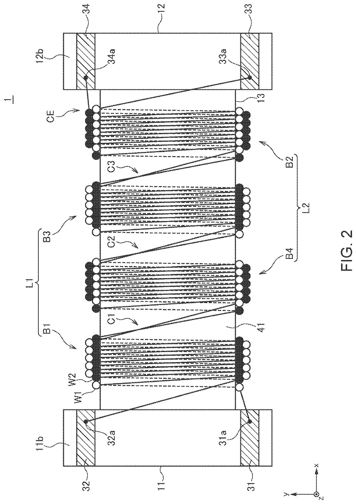
[0008]In the present invention, the first layer winding portion may further include a third block adjacent to the second block, the second layer winding portion may further include a fourth block adjacent to the first block, and the difference in the number of turns between the third and fourth blocks may be equal to or less than one. This can reduce the parasitic capacitance component. To further enhance the symmetr

Problems solved by technology

However, the winding method described in JP 2019-121791A cannot necessarily achieve sufficient symmetry between the pair of wires, with the result that mode conversio

Method used


Image

  • Common mode filter
  • Common mode filter
  • Common mode filter

Examples


Example

BRIEF DESCRIPTION OF THE DRAWINGS

[0018]Hereinafter, a preferred embodiment of the present invention will be described in detail with reference to the accompanying drawings.

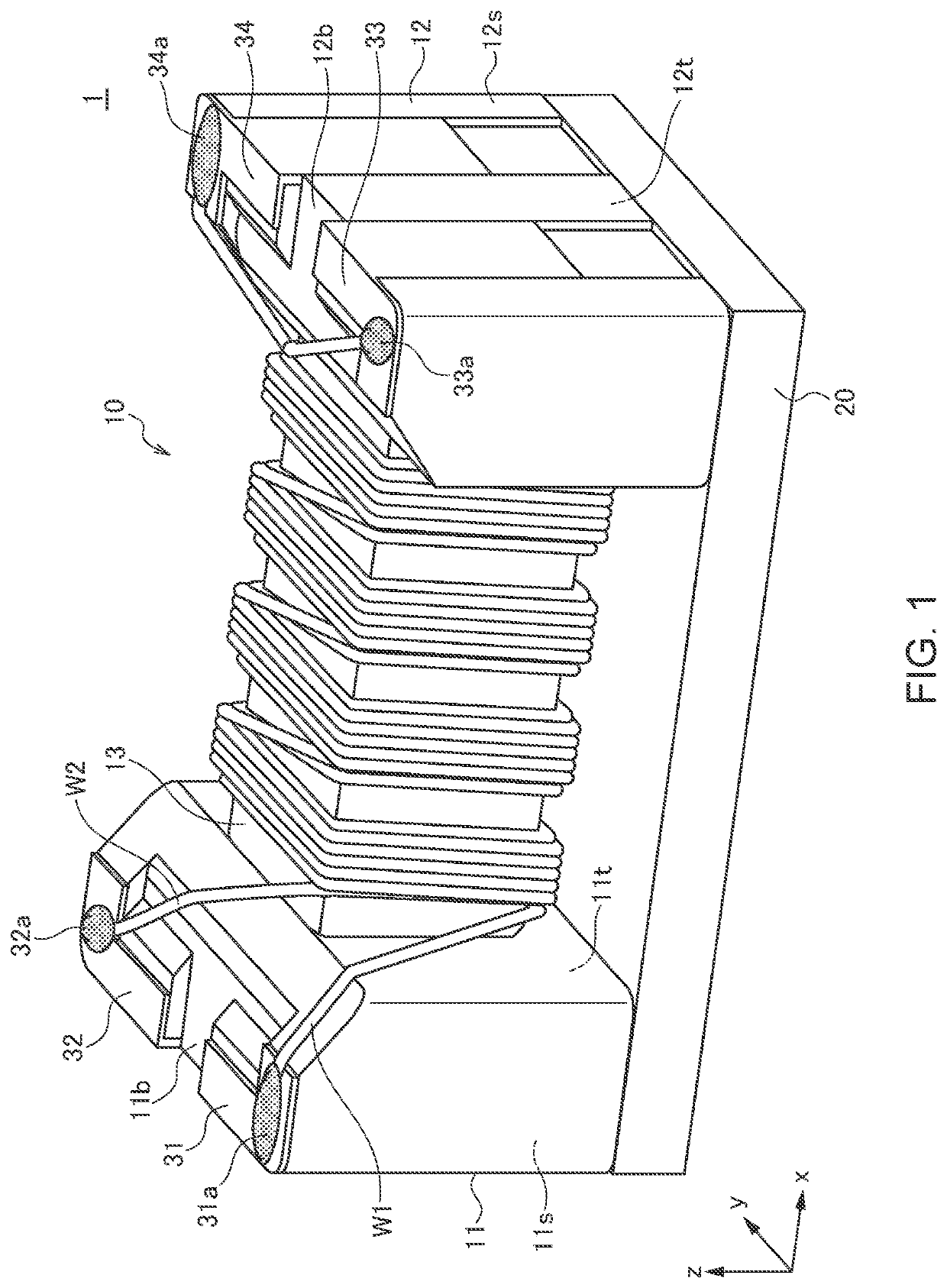
[0019]FIG. 1 is a schematic perspective view illustrating the outer appearance of a common mode filter 1 according to a first embodiment of the present invention.

[0020]As illustrated in FIG. 1, the common mode filter 1 according to the first embodiment includes a drum core 10, a plate core 20, first to fourth terminal electrodes 31 to 34, and first and second wires W1 and W2. The drum core 10 and plate core 20 are each made of a magnetic material such as an Ni—Zn based ferrite. The first to fourth terminal electrodes 31 to 34 are each a metal fitting made of a good conductor material such as copper. The first to fourth terminal electrodes 31 to 34 may be obtained by directly baking silver paste or the like onto the drum core 10.

[0021]The drum core 10 has a first flange part 11, a second flange part 12, and a windi...


PUM


Abstract

Disclosed herein is a common mode filter that includes first and second wires wound in the same direction around the winding core part. The first and second wires include first and second layer winding portions each including a plurality of blocks axially alternately arranged. A first block belonging to the first layer winding portion is disposed closest to the first flange part. A second block belonging to the second layer winding portion is disposed closest to the second flange part. The first and second wires cross each other in a region between axially adjacent blocks.

Description

BACKGROUND OF THE INVENTIONField of the Invention[0001]The present invention relates to a common mode filter and, more particularly, to a common mode filter of a type in which a pair of wires cross each other along the way and a manufacturing method therefor.Description of Related Art[0002]A common mode filter is widely used in many electronic devices, such as mobile electronic devices and on-vehicle LANs, as an element for removing common mode noise superimposed on differential signal lines. In recent years, a common mode filter using a surface-mountable drum core supersedes a common mode filter using a toroidal core (see JP 2019-121791A). In the common mode filter described in JP 2019-121791A, a pair of wires are wound in odd-numbered blocks. Further, the pair of wires are reversed in vertical position between adjacent blocks and cross each other in a region between adjacent blocks.[0003]In the winding method described in JP 2019-121791A, the vertical positions of the pair of wire...

Claims


Application Information

Patent Timeline
IPC IPC(8): H01F17/04H01F27/29H01F27/28H01F27/30
CPCH01F17/045H01F27/292H01F2017/0093H01F27/306H01F27/2828H01F27/34H01F17/04H01F27/2823H01F41/069
Inventor KUNITSUKA, KOSUKEHIGASHIDA, KEIGOITO, EMI
Owner TDK CORPARATION
Learn More