
Coil component

a technology of components and coils, applied in the direction of transformer/inductance details, inductance with magnetic cores, electrical devices, etc., can solve the disadvantage of large parasitic capacitance components, and achieve the effect of preventing an increase of parasitic capacitance components

Active Publication Date: 2020-07-30
TDK CORPARATION
View PDF3 Cites 0 Cited by
  • Summary
  • Abstract
  • Description
  • Claims
  • Application Information

AI Technical Summary

Benefits of technology

The present invention aims to reduce a parasitic capacitance component in a coil component that has two wires wound in multiple layers. It achieves this by arranging the turns of the wires in different layers so that the effect of neighboring turns with a large difference in turn number is minimized. This results in a regular winding structure that prevents an increase in parasitic capacitance component. The invention also proposes different ways of winding the first and second wires to achieve a four-layered structure.

Problems solved by technology

However, in the winding structure disclosed in JP 1999-74133A (FIGS. 6 to 8), turns between which a difference in turn number is large are adjacent to each other, so that a large parasitic capacitance component is disadvantageously generated.

Method used


Image

  • Coil component
  • Coil component
  • Coil component

Examples


Embodiment Construction

[0035]Preferred embodiments of the present invention will be explained below in detail with reference to the accompanying drawings.

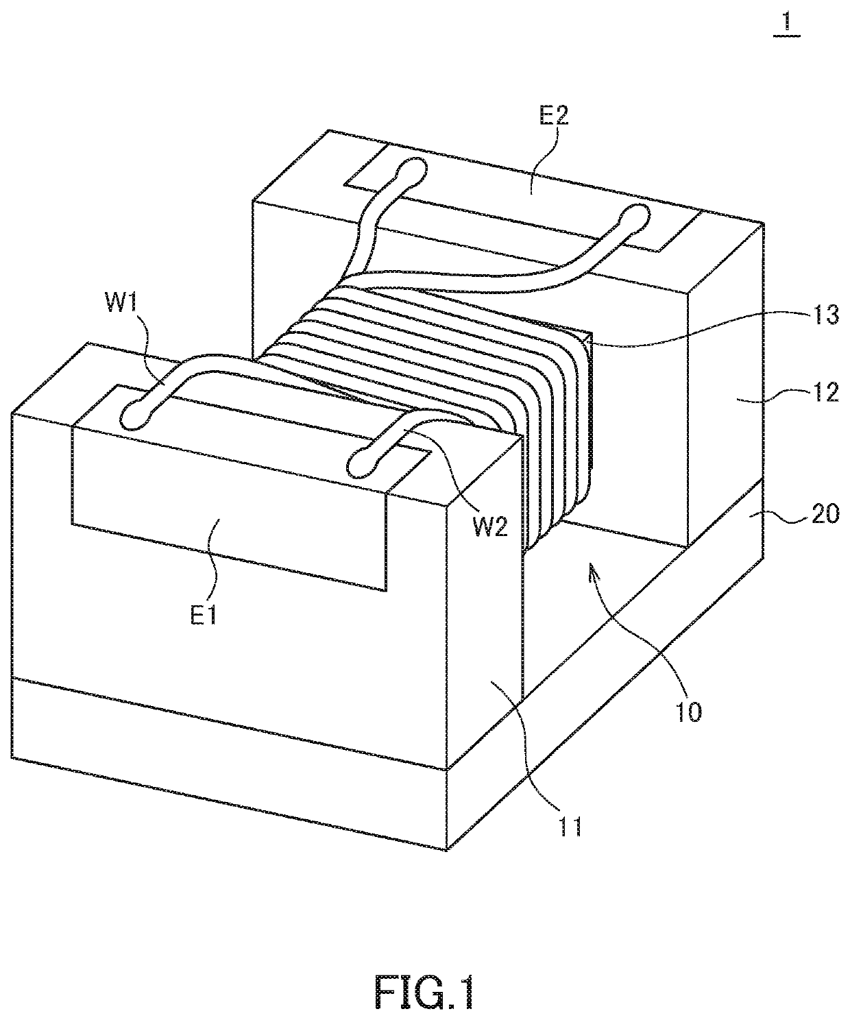
[0036]FIG. 1 is a schematic perspective view illustrating the outer appearance of a coil component 1 according to a preferred embodiment of the present invention.

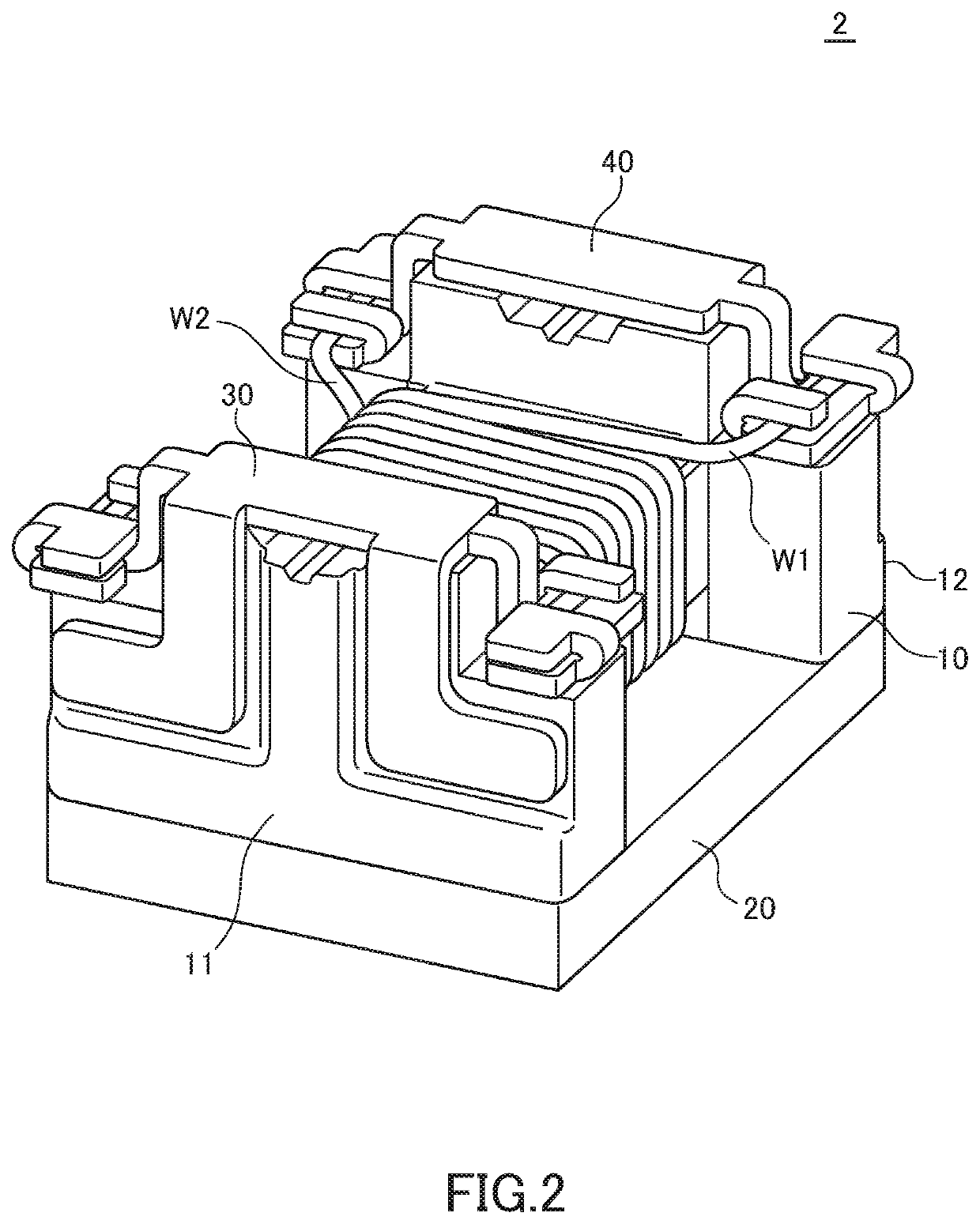
[0037]As illustrated in FIG. 1, the coil component 1 according to the present embodiment includes a drum-shaped core 10 having flange parts 11 and 12 and a winding core part 13, a plate-shaped core 20 fixed to the flange parts 11 and 12, a terminal electrode E1 provided on the flange part 11, a terminal electrode E2 provided on the flange part 12, and wires W1 and W2 wound around the winding core part 13. The wires W1 and W2 are each a coated conductive wire with a good conductor such as copper as a core material.

[0038]The core 10 is a drum-shaped block made of a high-permeability material such as ferrite and has a structure integrating the flange parts 11, 12 and the winding core part 13 provid...


PUM

PropertyMeasurementUnit
inductanceaaaaaaaaaa
lengthaaaaaaaaaa
DC resistanceaaaaaaaaaa

Abstract

Disclosed herein is a coil component that includes a winding core part, and first and second wires wound around the winding core part. The first and second wires constitute at least three winding layers on the winding core part. A i-th (i is an integer equal to or larger than 1) turn, a (i+1) turn, and a (i+2) turn of each of the first and second wires are positioned in mutually different winding layers.

Description

BACKGROUND OF THE INVENTIONField of the Invention[0001]The present invention relates to a coil component and, more particularly, to a coil component in which a wire is wound around a winding core part thereof in multiple layers.Description of Related Art[0002]To increase the inductance of a coil component in which a wire is wound around a winding core part thereof, it is necessary to increase the number of turns of the wire. However, when the wire is wound around a winding core part in a single layer, the length necessary for the winding core part is increased in proportion to the number of turns. Thus, in order to increase the number of turns of the wire while suppressing an increase in the length of the winding core part, the wire needs to be wound around the winding core part in multiple layers as described in JP 1999-74133A.[0003]Meanwhile, the coil component mainly used in a power supply circuit is required to provide low DC resistance and high rated current. In order to satisf...

Claims


Application Information

Patent Timeline
Patent Type & Authority Applications(United States)
IPC IPC(8): H01F27/28H01F27/29H01F27/24H01F41/069
CPCH01F27/2823H01F41/069H01F27/24H01F27/29H01F17/04H01F27/34H01F27/263H01F27/006Y10T29/5313
Inventor YOSHINO, HANAKOSUZUKIURABE, DAISUKEHIGASHIDA, KEIGOTSUCHIYA, TOMOKAZU
Owner TDK CORPARATION
Learn More