
Methods for calculating real time package density

a technology of real-time package density and method, applied in the field of methods for calculating real-time package density, can solve the problems of lack of real-time package scans, inability to assess the real-time package density within an uld, and traditional methods consistently fail to provide accurate real-time package density measurements

Active Publication Date: 2021-12-23
ZEBRA TECH CORP
View PDF0 Cites 0 Cited by
  • Summary
  • Abstract
  • Description
  • Claims
  • Application Information

AI Technical Summary

Benefits of technology

The present invention provides a machine-readable medium that includes instructions for assessing the density of a unit load device (ULD) package. The machine captures images of the ULD and a secondary image, which include 3D image data. The image data is segmented, and the depth values of each segment are determined. The depth change between the two images is calculated, and subsections of the secondary image are clustered based on their depth values. The wasted volume is then calculated by multiplying the depth values of the clusters with an area value, and the ULD package density is calculated by subtracting the wasted volume from the filled volume.

Problems solved by technology

Presently, no method exists for assessing the real-time package density within a ULD when the packages are not loaded in a manner sufficient to fill most wasted space within the ULD.
Unfortunately, these traditional methods typically require package feed integration and suffer from a lack of real-time package scans.
As a result, traditional methods consistently fail to provide accurate, real-time package density measurements.
However, these traditional imaging systems suffer from a number of drawbacks, such as being unable to effectively determine ULD package density for ULDs placed within the system's field of view (FOV).
However, this procedure requires customer integration and does not include real-time package scans.
As a result, the traditional imaging systems and methods fail to provide accurate or real-time package density determinations.
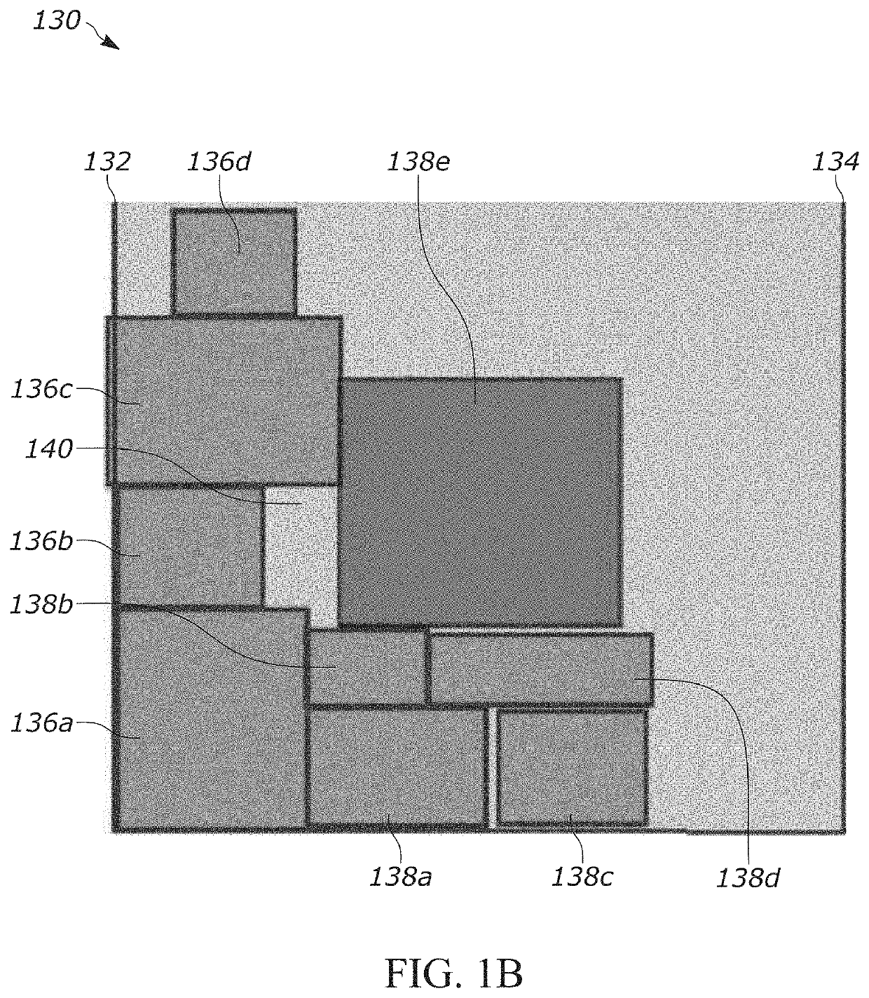
If there is a protrusion in the packages behind a newly placed package, there must be wasted space, as the newly placed package is constrained to move as far back in the ULD as the furthest forward surface of packages behind the newly placed package allows.
Conventional systems are unable to identify such wasted space within ULDs during a loading session, and as a result, fail to account for the wasted space in any performed loading analytics.
For example, if the back wall of the ULD is six meters away, the LMU should not cluster the eight subsections with a secondary largest depth value of six meters because the LMU would be improperly categorizing the back wall as an “object.” Doing so may cause the LMU to lose resolution during subsequent iterations of the method 400 because the LMU may be unable to determine smaller packages and other objects within the ULD if four fifths of the ULD is treated as a single cluster.

Method used


Image

  • Methods for calculating real time package density
  • Methods for calculating real time package density
  • Methods for calculating real time package density

Examples


Embodiment Construction

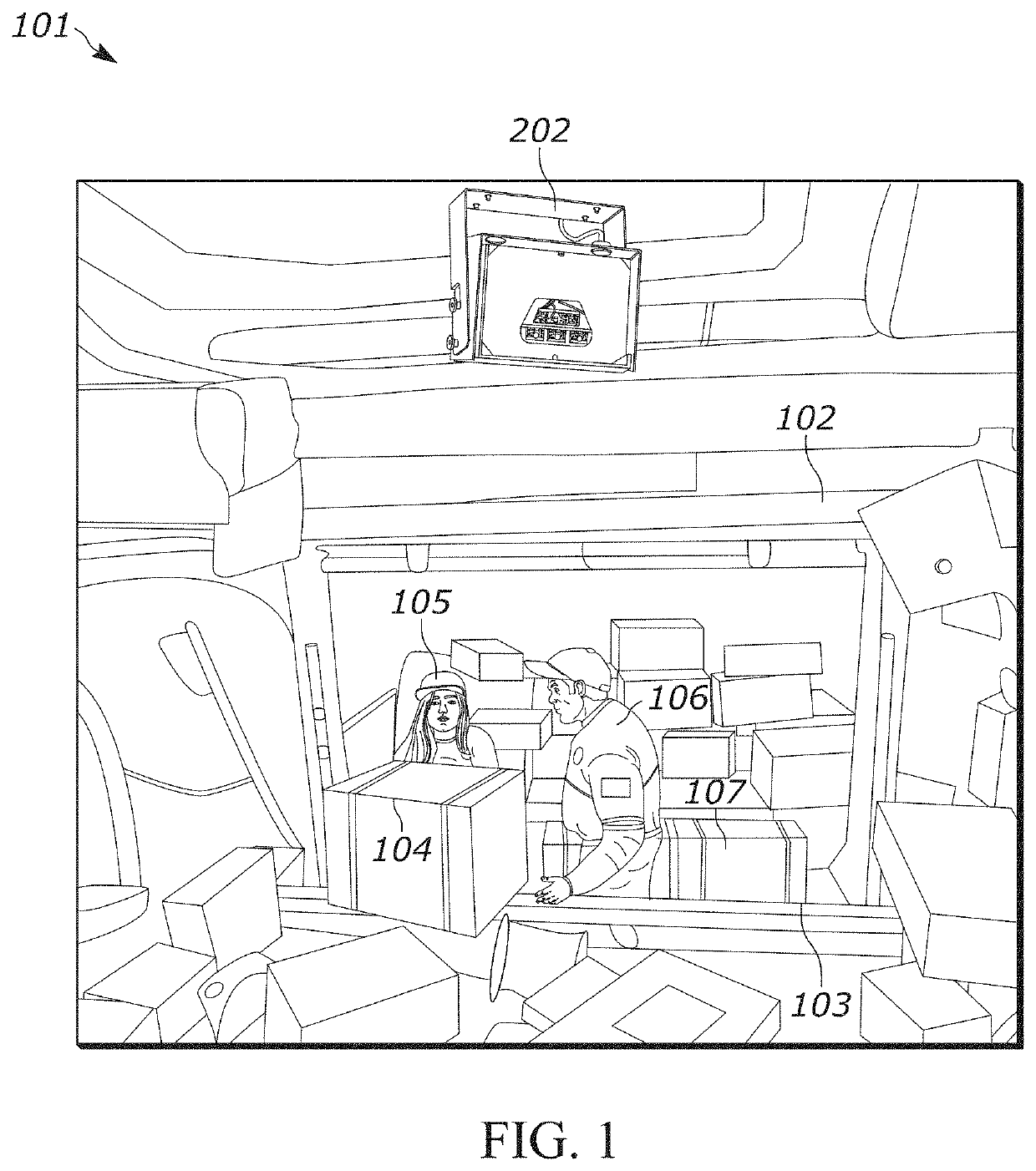
[0032]Generally speaking, shipping companies seek to accurately and efficiently detail the load status of each container for which they are responsible. Many companies incorporate imaging systems to provide this analysis (e.g., LMUs). However, these traditional imaging systems suffer from a number of drawbacks, such as being unable to effectively determine ULD package density for ULDs placed within the system's field of view (FOV). For example, package scans are presently required to give the volume of the packages loaded, which is then divided by the fullness. However, this procedure requires customer integration and does not include real-time package scans. As a result, the traditional imaging systems and methods fail to provide accurate or real-time package density determinations.

[0033]Consequently, the methods / systems of the present disclosure provide solutions to the ULD package density assessment problems associated with the traditional systems. Namely, the present disclosure ...


PUM


Abstract

Methods and systems for assessing a unit load device (ULD) package density are disclosed herein. An example method includes capturing a primary and secondary image featuring the ULD. The method further includes segmenting the primary image and the secondary image into a plurality of subsections and determining a primary largest depth value and secondary largest depth value for each subsection. The method further includes determining a depth change by comparing the primary largest depth value for each subsection to the secondary largest depth value for each subsection. The method further includes clustering subsections in the secondary image including a respective secondary largest depth value that is substantially similar to a subsection corresponding to a depth change to create a plurality of clusters. The method further includes calculating a wasted volume, and calculating a ULD package density by subtracting the wasted volume from a filled volume of the ULD.

Description

BACKGROUND[0001]In commercial shipping via airplanes, packages are loaded into containers called unit load devices (ULDs). Typically, load monitoring units (LMUs) or other devices capture images of the ULDs during loading to track loading progress. More recently, LMUs also perform real-time analytics using the ULD images to actively assess various aspects of the loading procedure, such as package density. Shipping companies increasingly rely on LMU package density analytics to determine the efficiency of their packing / unpacking procedures. Moreover, package density analytics typically inform loaders and other personnel when a loading session is considered complete, and when a container may be loaded for transport. Correspondingly, a major point of emphasis in the shipping industry is ensuring that LMUs perform high-fidelity, real-time package density analytics during ULD loading sessions.[0002]Presently, no method exists for assessing the real-time package density within a ULD when ...

Claims


Application Information

Patent Timeline
Patent Type & Authority Applications(United States)
IPC IPC(8): G06T7/62G06T7/11G06T7/55G06T5/20G06T5/00
CPCG06T7/62G06T7/11G06T7/55G06T2200/04G06T5/002G06T2207/10024G06T2207/10048G06T5/20G06T2207/10012G06T5/70
Inventor BARISH, JUSTIN F.
Owner ZEBRA TECH CORP
Learn More