

Inkjet print apparatus and inkjet print method
- Summary
- Abstract
- Description
- Claims
- Application Information
AI Technical Summary
Benefits of technology
Problems solved by technology
Method used
Image

Examples
first embodiment
[0023]An embodiment according to the present invention will be described below in detail with reference to the accompanying drawings. The term “print” in the specification includes not only the formation of significant information such as text or graphics on a print medium, but also the formation of non-significant information on a print medium. Also, the term “print medium” represents not only paper used in a typical print apparatus, but also an ink receptive item such as cloth, a plastic film, a metal plate, glass, ceramics, wood, leather or the like. Also, the term “ink” should be widely interpreted as in the case of the definition of the term “print”, and is assumed as an item which can form an image, design, pattern or the like by being applied to a print medium.
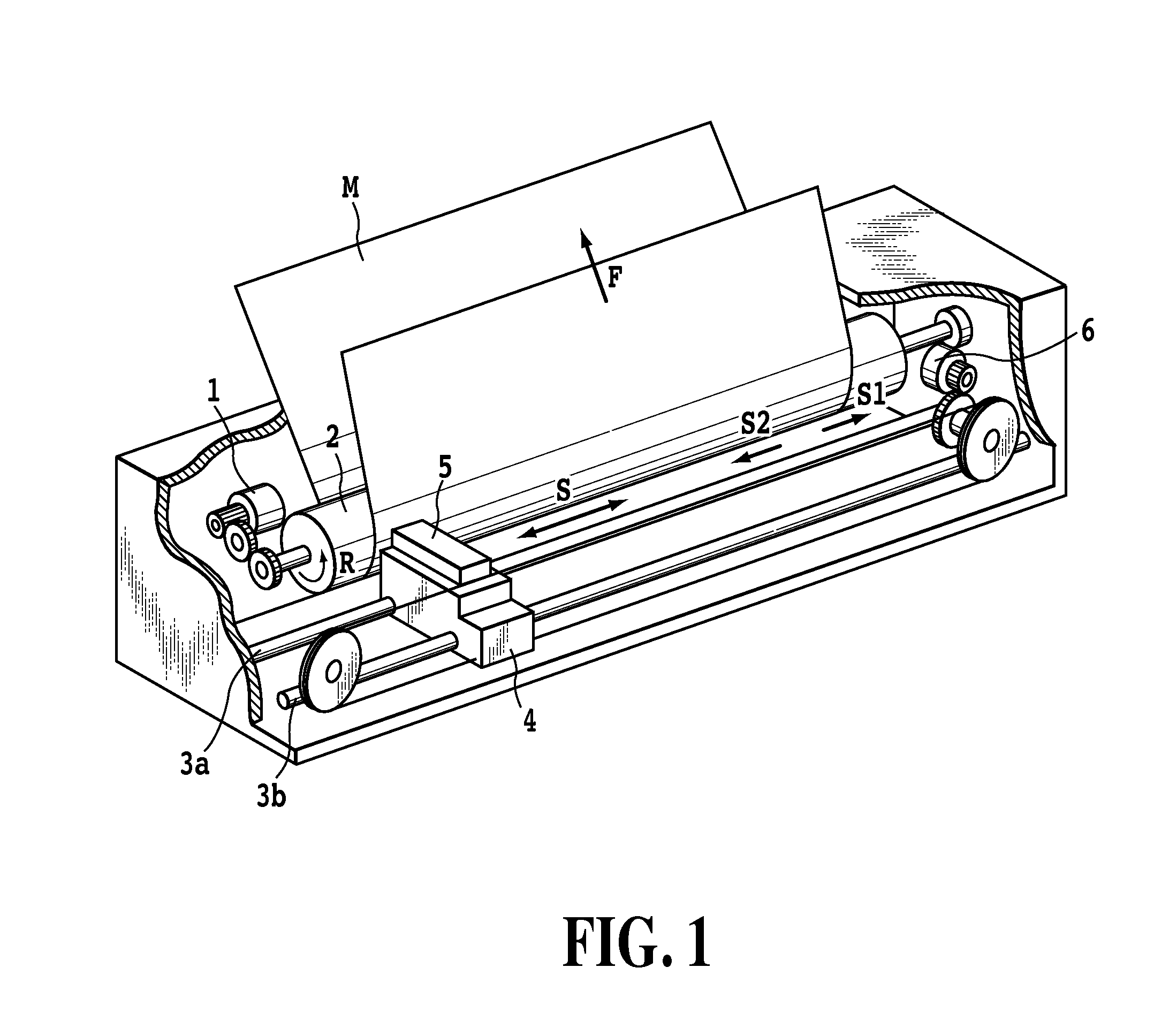
[0024]FIG. 1 is a schematic perspective view illustrating the internal mechanism of an inkjet print apparatus which can be suitably employed in the present embodiment. A line feed motor 1 is driven in order to rotate a ...
second embodiment
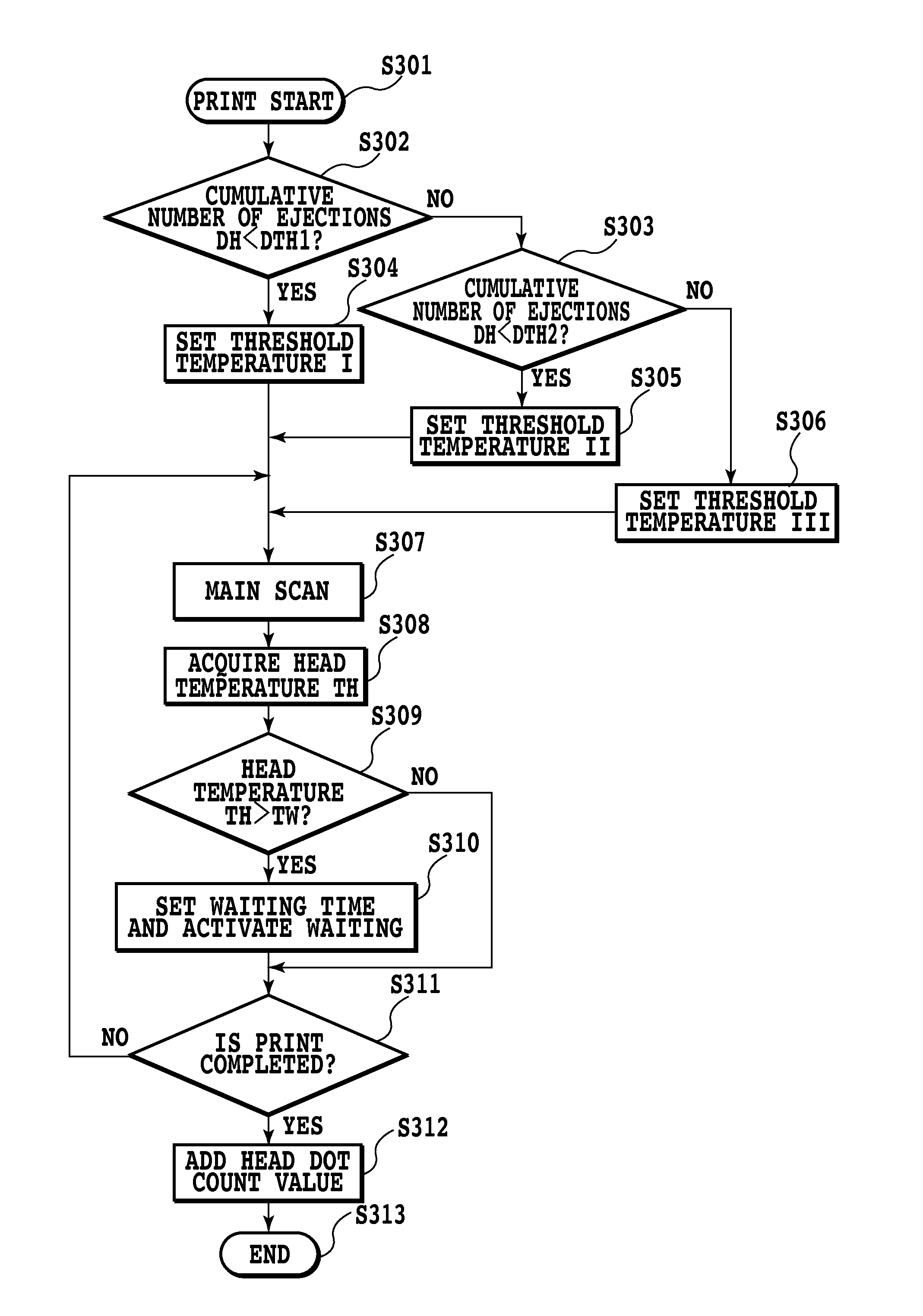
[0042]In the first embodiment, the cumulative number of ejections of the print head (head dot count value DH) is counted irrespective of the temperature of the print head, and the threshold temperature is changed in accordance with the counted number. In the second embodiment, the number of ejections from the print head in a state of a predetermined temperature or higher is counted and the threshold temperature is controlled to be decreased in accordance with the counted number.
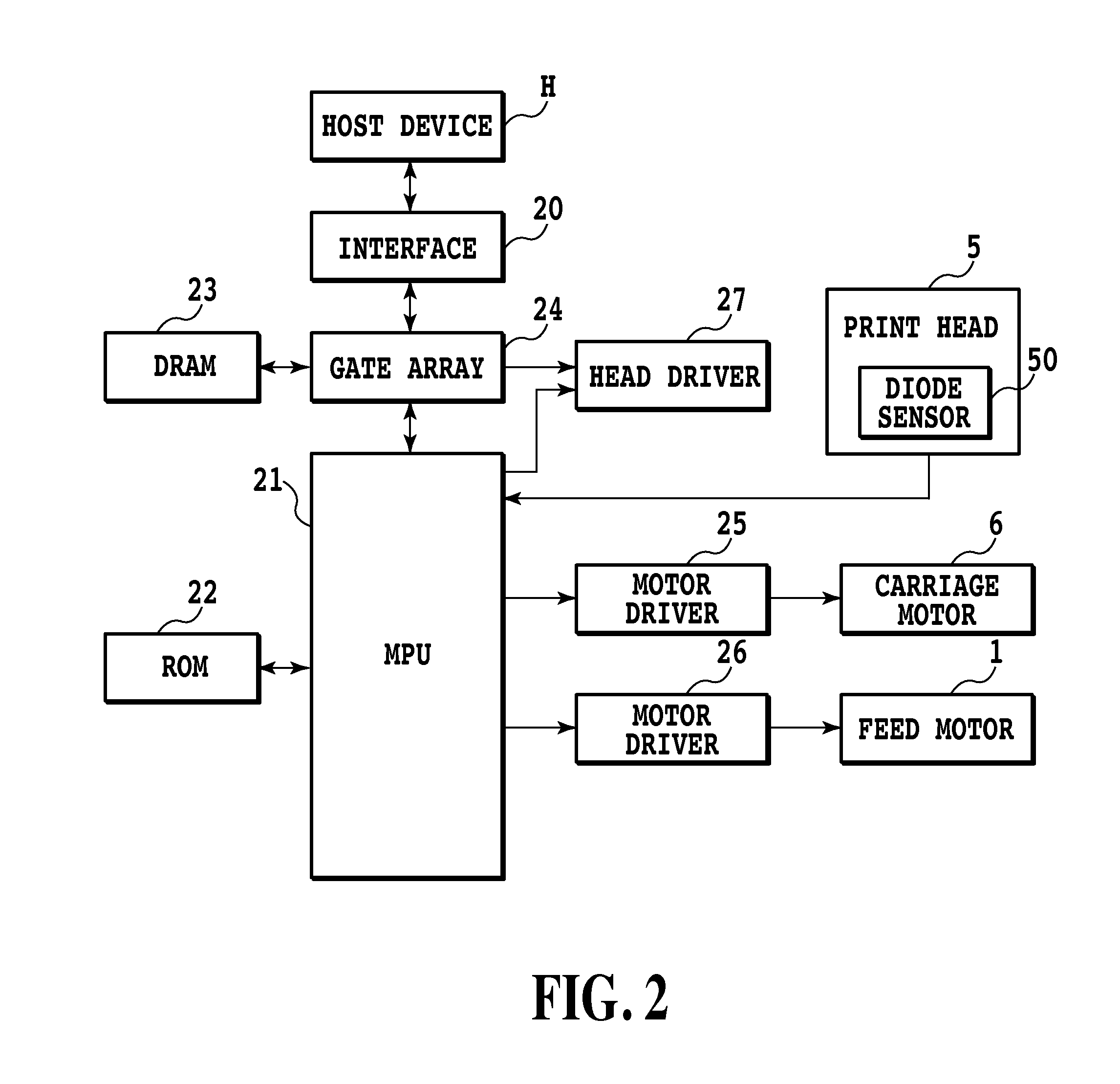
[0043]FIG. 6 is a flowchart describing a series of process steps executed by the MPU 21 for printing the image for one page in the print apparatus of the second embodiment. Upon start of print (step S601), the MPU 21 receives image data including control data from the host device H through the interface 20 and the gate array 24.
[0044]Next, the MPU 21 reads the cumulative number of ejections from the print head at a predetermined temperature or higher (hereinafter, also referred to as “head dot count value DH2...
PUM
 Abstract
Description
Claims
Application Information