Rod rotation apparatus

a technology of rotating rods and rods, which is applied in the direction of hand cart accessories, other accessories, hand carts with multiple axes, etc., can solve the problems of increased weight of rods, increased rods can be easily deformed, and rod length is bound to be long, so as to prevent the phenomenon

Pending Publication Date: 2021-12-30
CHO WONSANG
View PDF0 Cites 2 Cited by
  • Summary
  • Abstract
  • Description
  • Claims
  • Application Information

AI Technical Summary

Benefits of technology

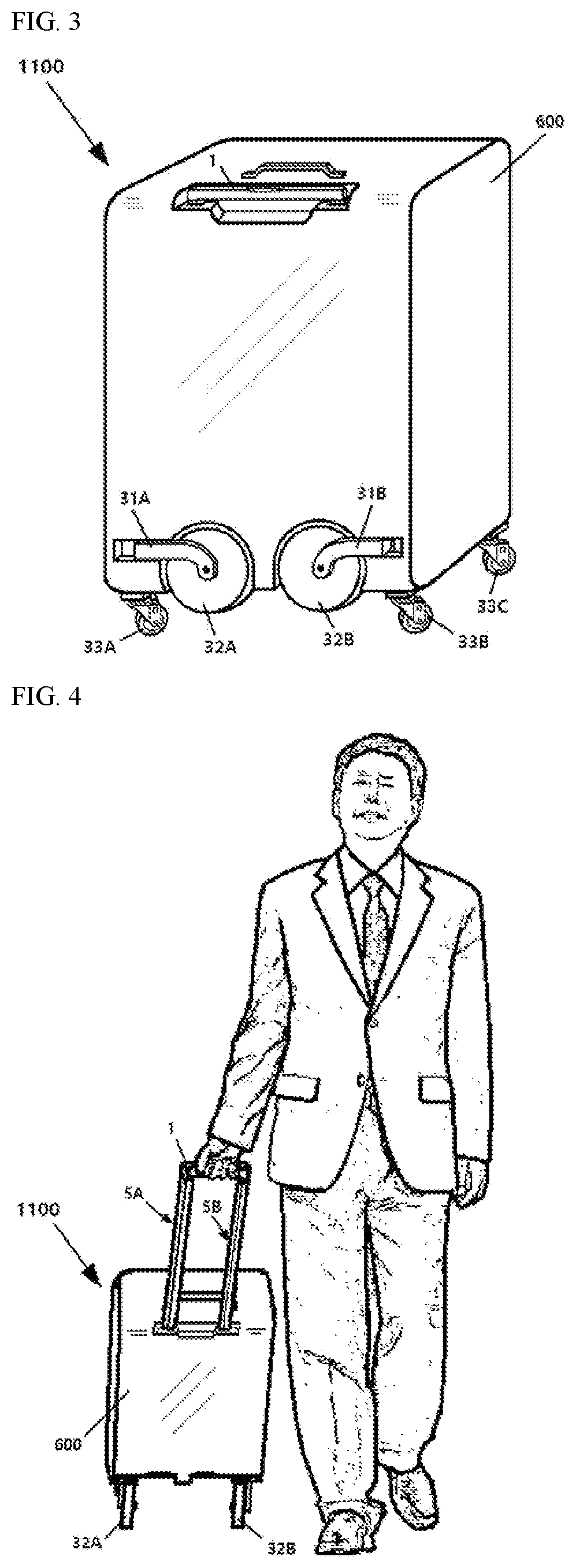
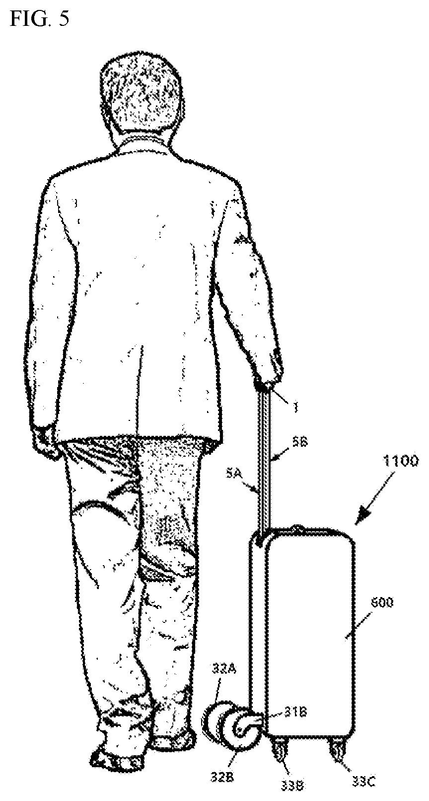
[0042]According to the present invention, it is possible not only to cause a pair of wheels to be unfolded by moving the handle of a carrier up or to cause the pair of wheels to be folded by moving the handle down, but also to cause the pair of wheels to be folded even when the handle is lifted up to a predetermined height above the upper part of the body.
[0043]Therefore, not only may the carrier be pulled by using a pair of wheels that are spread out forward by lifting the handle up high, but also it is possible to effectively prevent the phenomenon that the foot hits the pair of wheels when the carrier is pushed and moved by using a plurality of the caster wheels attached to the bottom of the body while holding the handle by hand with it lifted up to a predetermined height and with the pair of wheels folded and with the carrier upright.

Problems solved by technology

The “WHEELED LUGGAGE” disclosed in the Republic of Korea Patent Publication No. 10-2015-0084422, however, has the inconvenience that its weight is increased and the rods can be more easily deformed from external impacts because the distance between the vertical sections of the helixes formed on the rods is longer than the vertical movement distance of the handle; therefore, the length of the rods is bound to be long.
Regarding the ‘LUGGAGE WITH FOLDING WHEELS’ disclosed in the Republic of Korea Patent Publication No. 10-2017-0035182, it is only possible to unfold the pair of wheels forward by pulling the handle up or to fold the pair of wheels by pushing the handle down, but it is not possible to have the pair of wheels folded while the handle is moved upward by a predetermined distance.
Therefore the ‘LUGGAGE WITH FOLDING WHEELS’ disclosed in the Republic of Korea Patent Publication No. 10-2017-0035182 has the inconvenience that the pair of wheels spread out forward may interfere with walking by being struck by the foot when pushing the carrier while it is upright by holding the handle pulled up and by using the caster wheels attached to the bottom of the carrier body.

Method used


Image

  • Rod rotation apparatus
  • Rod rotation apparatus
  • Rod rotation apparatus

Examples


seventh embodiment

[0466]FIG. 33 is a perspective view showing a rod rotation apparatus according to the seventh embodiment of the present invention and carrier 1700 including the apparatus.

[0467]Hereinafter, likewise, descriptions of contents overlapping with the above-described embodiments may be omitted.

[0468]Just as traction member housing 102 is attached to movable member 20 included in carrier 1600 of FIG. 25, one or more traction member housings 114A and 114B are also attached to movable member 20 included in carrier 1700 of FIG. 33.

[0469]The shape and structure of traction member housings 114A and 114B are exemplary, and the present invention is not limited thereto.

[0470]FIG. 34 exemplarily shows a state in which guide member 47A and guide member 47B are removed and a part of each of traction member housing 114A and traction member housing 114B is cut and removed from carrier 1700 of FIG. 33

[0471]Referring to carrier 1700 of FIG. 33, traction members 111A and 111B are connected between movable...

eighth embodiment

[0495]FIG. 39 is a perspective view showing a rod rotation apparatus according to the eighth embodiment of the present invention and carrier 1800 including the apparatus.

[0496]Hereinafter, likewise, description of the content overlapping with the above-described embodiments will be omitted.

[0497]Carrier 1800 of FIG. 39 is similar to carrier 1700 of FIG. 33 except that handle extender 86A and handle extender 86B each have a two-stage structure, and restoration member housing 121 is attached to body 610.

[0498]As shown in FIG. 43, restoration member 134 is positioned inside restoration member housing 121, and thus restoration member 134 is coupled to or installed on body 610.

[0499]Restoration member housing 121 includes therein restoration member 134 as shown in FIG. 43.

[0500]Traction member 111A is connected between movable member 20 and handle extender 86A, and similarly, traction member 111B is connected between movable member 20 and handle extender 86B.

[0501]The lower portion of tr...

tenth embodiment

[0611]FIG. 51 is a perspective view showing a rod rotation apparatus according to the tenth embodiment of the present invention and carrier 2000 including the apparatus.

[0612]Hereinafter, likewise, description of the content overlapping with the above-described embodiments will be omitted.

[0613]Carrier 2000 of FIGS. 51, 53, and 54 are the same as carrier 1900 of FIGS. 44, 50, and 48, respectively, except that guide member 47A and guide member 47B are coupled to body 610 instead of guide member 48A and guide member 48B.

[0614]FIG. 52 shows a state in which guide member 47A and guide member 47B are removed from carrier 2000 of FIG. 51.

[0615]Traction members 141A and 141B are connected between movable member 20 and handle extender 46A and 46 in order to pull movable member 20 included in carrier 2000 by a predetermined distance in a predetermined direction.

[0616](Movable member 20 may be pulled upward by a predetermined distance by one or more traction members 141A and 141B.)

[0617]Refer...


PUM


Abstract

An exemplary embodiment of the present invention provides a rod rotation apparatus, including: a rod having at least one first helix or at least one second helix coupling portion; a movable member having at least one first helix coupling portion or at least one second helix coupled with the at least one first helix or the at least one second helix coupling portion; a handle extender having a structure of one or more stages, including a first-stage extender; a handle coupled to the top of the handle extender; and a traction member connected between the movable member and the handle or between the movable member and the handle extender.

Description

TECHNICAL FIELD[0001]The present invention relates to a rod rotation apparatus, and more particularly, to a rod rotation apparatus that can be applied to folding or unfolding a wheel and to a carrier including the apparatus.BACKGROUND ART[0002]‘WHEELED BAG’ (English title of the invention: ‘WHEELED LUGGAGE’, Republic of Korea Patent Publication No. 10-2015-0084422) and ‘WHEEL FOLDING CARRIER’ (English title of the invention: ‘LUGGAGE WITH FOLDING WHEELS’, Republic of Korea Patent Publication No. 10-2017-0035182) were filed by the applicant of the present application. Their pair of rather large wheels can be unfolded or folded as their handles are pulled up or down, respectively, and they are convenient to use even on the ground where the unevenness is rather severe, and they are also convenient for storage as the wheels can be simply folded when not in use.[0003]The “WHEELED LUGGAGE” disclosed in the Republic of Korea Patent Publication No. 10-2015-0084422, however, has the inconven...

Claims


Application Information

Patent Timeline
Patent Type & Authority Applications(United States)
IPC IPC(8): B62B5/06A45C5/14A45C13/26B62B3/02
CPCB62B5/067A45C5/146A45C2005/148B62B3/02A45C2013/267A45C13/262A45C2013/265A45C13/28
Inventor CHO, WONSANG
Owner CHO WONSANG
Why Eureka
Try Eureka