
Optical film, polarizing plate and liquid crystal display device

a technology of optical film and liquid crystal display device, which is applied in the direction of optics, polarizing elements, instruments, etc., can solve the problems of not revealing nor suggesting, increasing material costs or complicating the manufacturing process,

Active Publication Date: 2012-12-20
FUJIFILM CORP
View PDF11 Cites 12 Cited by
  • Summary
  • Abstract
  • Description
  • Claims
  • Application Information

AI Technical Summary

Benefits of technology

[0037]According to the present invention, it is possible to provide an optical film with a small change in dimension according to the change in temperature of a support of a pattern retardation film. In particular, in a 3D switchable image display panel, when an optical film having a first retardation region and a second retardation region is applied, in which birefringence is different from each other, and in which the first retardation region and the second retardation region are alternately patterned for every one line, the occurrence of contraction in a direction perpendicular to the pattern produces a misalignment between images of the panel, which is responsible for the crosstalk. However, it is possible to effectively prevent the phenomenon in the present invention.EMBODIMENTS FOR CARRYING OUT THE INVENTION
[0038]Hereinafter, embodiments of the present invention will be described in detail. The description of constituent elements described hereinafter may be made based on a representative embodiment of the present invention, but the present invention is not limited to such an embodiment. Further, in the present specification, “to” is used to mean that numerical values described before and after the term are included as a lower limit and an upper limit In addition, in the present specification, the inversion of the slow axis or the axis inversion refers to rotation of the slow axis at about 90° with respect to the original direction.
[0039]In the present specification, “parallel” and “perpendicular” mean a range within an exact angle less than ±10°. For the range, an error with the exact angle is preferably less than ±5° and more preferably less than ±2°. In addition, “substantially perpendicular” means a range within an angle of the exact vertical angle less than ±20°. For the range, an error with the exact angle is preferably less than ±15° and more preferably less than ±10°. Furthermore, “slow axis” means the direction in which the refractive index becomes the maximum. Further, the wavelength at which the refractive index is measured is a value in the visible region with λ=550 nm unless otherwise particularly described.
[0040]In the present specification, “polarizing plate” is used as a meaning including both a long polarizing plate and a polarizing plate cut (in the present invention, “cut” includes “punched”, “cut out” and the like) to a size which enables the polarizing plate to be inserted into a liquid crystal display device, unless otherwise particularly rejected. In addition, in the present specification, the “polarizer” and “polarizing plate” are used as different meanings, but the “polarizing plate” means a laminated body having a transparent protective film at least on one side of a “polarizer” to protect the polarizer.
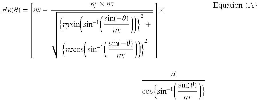
[0041]In the present description, Re (λ) and Rth (λ) represent an in-plane retardation and a retardation in a thickness-direction, respectively at a wavelength of λ. Re (λ) is measured by irradiating with an incident light with a wavelength of λ nm in the normal direction of a film using KOBRA 21ADH or WR (manufactured by Oji Scientific Instruments Co., Ltd.).
[0042]When a film to be measured is represented by a uniaxial or biaxial refractive index ellipsoid, Rth (λ) is calculated by the following method.

Problems solved by technology

For this reason, these documents do not disclose nor suggest the means or spirit of eliminating birefringence of some portions of a TAC film used as a protective film, or do not disclose the expression of birefringence to the TAC film itself or the precision of forming a pattern.
In addition, there is dissatisfaction with the methods of Patent Documents 3 to 5, including: disposing the slow axes of two materials with different birefringence by transferring, for example, at 90°, and etching or physically cutting unnecessary portions after patterning, from the viewpoint of increasing material costs or complicating the manufacturing process.
Furthermore, it could be understood that any of the methods in Patent Documents 1 to 5 is not appropriate for the continuous film formation of a pattern retardation film and is an insufficient method, and requires to further reduce preparation costs.
Accordingly, there is dissatisfaction with pattern retardation films having regions having different birefringence from each other, which have been known so far, from the viewpoint of preparation costs.

Method used


Image

  • Optical film, polarizing plate and liquid crystal display device
  • Optical film, polarizing plate and liquid crystal display device

Examples


example

[0287]Hereinafter, the present invention will be described in more detail with reference to Examples. Materials, reagents, material amounts and proportions thereof, operations and the like shown in the following Examples may be appropriately changed as long as the spirit of the present invention is not deviated therefrom. Accordingly, the scope of the present invention is not limited to the following specific Examples.

[0288][Preparation Example of Support Film]

[0289](Support Film 1)

[0290]A dope is prepared by introducing 100 parts by mass of a cellulose acetate having a degree of substitution of 2.86 (the viscosity average polymerization degree is 300, the degree of substitution of acetyl groups at 6-position is 0.89, the acetone extraction portion is 7% by mass, the molecular weight ratio of mass average molecular weight / number average molecular weight is 2.3, the water content is 0.2% by mass, the viscosity in a 6 mass % dichloromethane solution is 305 mPa·s, the residual acetic a...


PUM


Abstract

There is provided an optical film having a small size change with a temperature change of a support of a pattern retardation film.An optical film includes: a support comprising a polymer having a moisture permeability of 0.5% or more; a first retardation region and a second retardation region, in which birefringence thereof is mutually different; and an optically anisotropic layer in which the first retardation region and the second retardation region are alternately patterned for every one line.

Description

TECHNICAL FIELD[0001]The present invention relates to an optical film, a polarizing plate and a liquid crystal display device. More specifically, the present invention relates to a 2D / 3D switchable image display panel and a 2D / 3D switchable image display system, which may display stereoscopic images and 2-dimensional images, and a pattern retardation film used in the image display panel.BACKGROUND ART[0002]In the 3D stereoscopic image display field in which a projected image is stereoscopically viewed as if the image is emerging and a powerful image may be enjoyed, recently, as 3D movies have been rapidly adopted by the general public, the 3D stereoscopic image display on a flat panel display, which is a closer scene, is beginning to draw great attention. In the related art, various modes in which images are stereoscopically viewed by naked eyes, or various modes in which dedicated glasses for watching stereoscopic images are used have been known in the stereoscopic display, but, un...

Claims


Application Information

Patent Timeline
IPC IPC(8): G02F1/1335G02B5/30G02B30/25
CPCH04N13/337G02B5/3033G02B5/30G02F1/13363
Inventor YANAI, YUJIROSATA, HIROAKINAKAYAMA, HAJIMESASADA, YASUYUKI
Owner FUJIFILM CORP
Learn More