
Relay block

a relay block and block technology, applied in the field of relay blocks, can solve the problems of reducing the space permitted for relay blocks in a highly densified engine room, changing the size of the socket portion, and changing the structure of the relay block, so as to reduce the melt viscosity of resin and reduce the dimensional change

Inactive Publication Date: 2005-08-04
ASAHI KASEI CHEM CORP
View PDF15 Cites 1 Cited by
  • Summary
  • Abstract
  • Description
  • Claims
  • Application Information

AI Technical Summary

Benefits of technology

"The present invention provides a novel relay block that satisfies all of the requirements for recent relay blocks, including reduction of melt viscosity, absence of melt wrinkles, and absence of melt wrinkles on the surface of the molded block. The relay block also has a high degree of deformation between parallel planes, a high degree of deformation at the periphery of a slit, a high degree of deformation at the periphery of a slit when a block copolymer is used, a high degree of deformation when a flame retardant is added, a high melt volume rate, a low dimensional change after water absorption, a low shrinkage anisotropy, a high weight per one gate in molding, a high degree of deformation at the periphery of a slit when a block copolymer is used, and a high degree of deformation when a flame retardant is added. The resin composition used in the relay block contains a polyamide, a polyphenylene ether, and a block copolymer."

Problems solved by technology

Nevertheless, at present, the space permitted for relay blocks in a highly densified engine room becomes smaller and smaller.
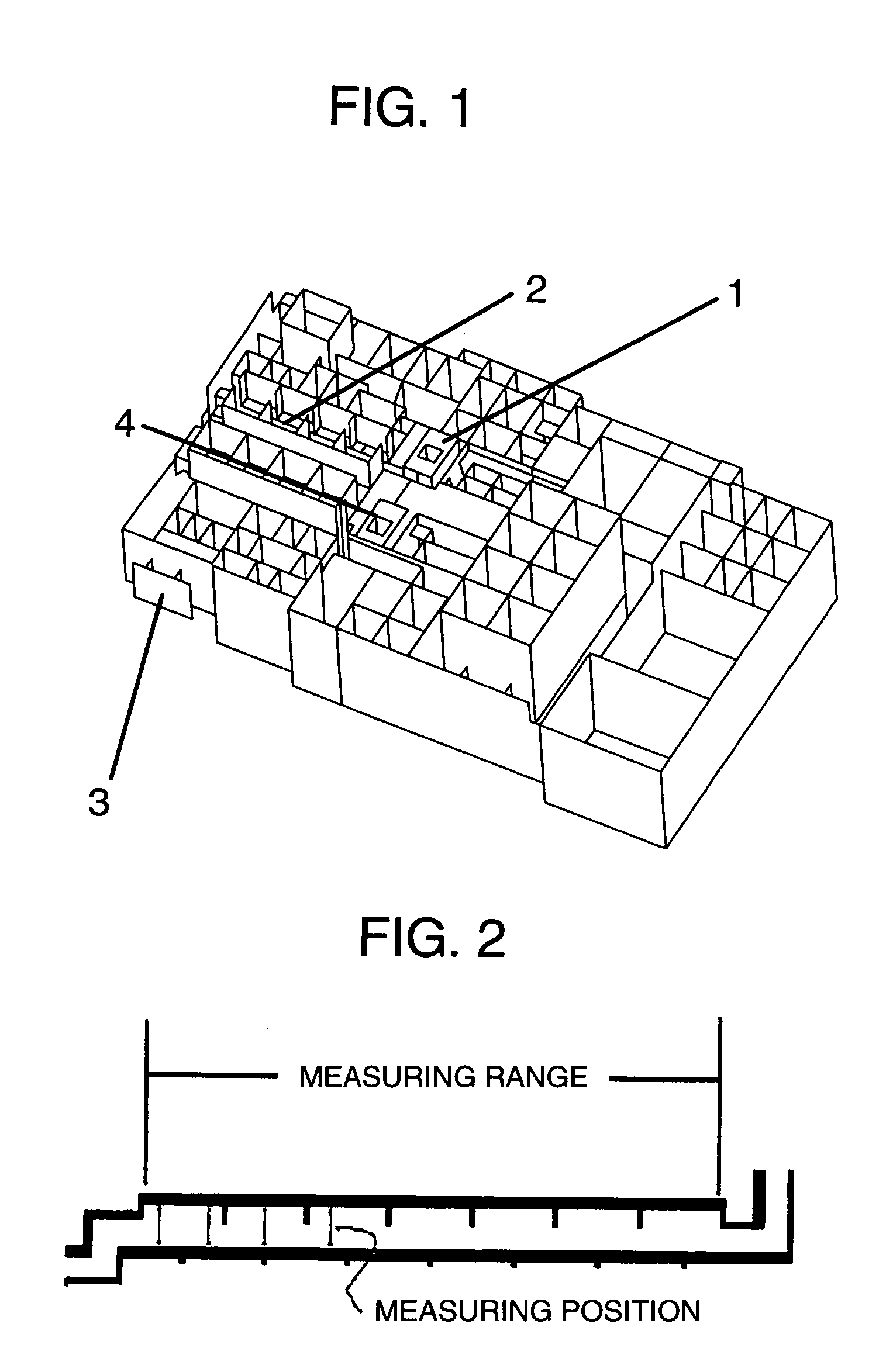
Thus, for disposing the relay block in a limited space, the structure of a relay block is very complicated and simultaneously the molded product has many thin wall portions.
However, in the case of reducing the rate of solidification, the after-shrinkage of molded products becomes great, which causes problems in a use such as relay blocks which are exposed to various environments after molding.
On the other hand, in relay blocks having a complicated structure, if the rate of dimensional change caused by water absorption is great, the size of the socket portion changes and the socket cannot be drawn out or the socket falls off.
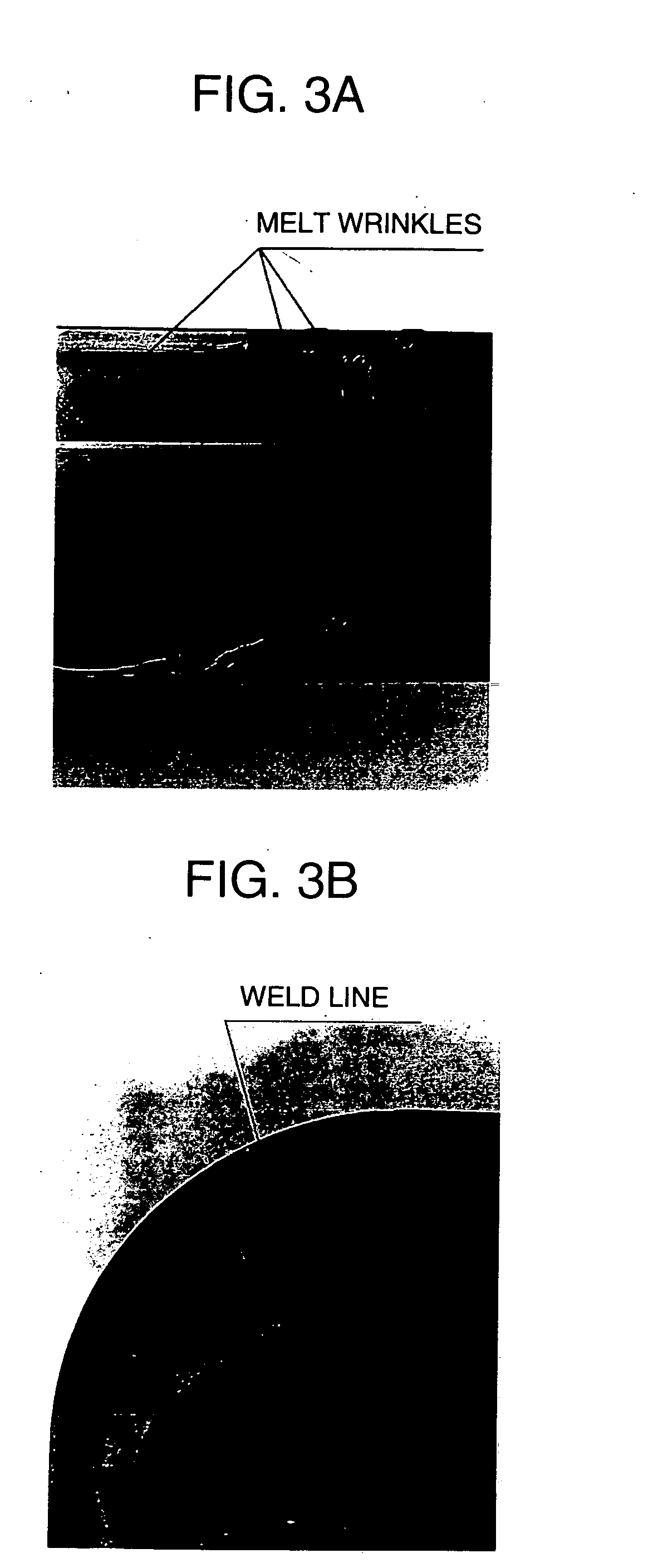
This causes not only a problem in appearance, but also is apt to become a starting point of cracking caused by vibration fatigue during operation for a long time, if the melt wrinkles are present on the stress generation portion, and, in the worst case, results in breakage.

Method used


Image

  • Relay block
  • Relay block
  • Relay block

Examples


example 1

[0224] The cylinder temperature of a twin-screw extruder [ZSK-40 manufactured by Werner & Pfleiderer GmbH (Germany)] having one feed opening on the upstream side and one feed opening in the central part of the extruder was set at 320° C. in the area from the upstream side feed opening (hereinafter abbreviated as “main-F”) up to the central feed opening (hereinafter abbreviated as “side-F”) of the extruder and at 280° C. in the area from side-F up to the die.

[0225] In accordance with the proportions shown in Table 1, PPE-L, SEBS-1 and 0.2 part by weight of maleic anhydride (hereinafter abbreviated as “MAH”) as a compatibilizer which were uniformly mixed were fed from main-F, and PA 6,6-3 in the proportion shown in Table 1 was fed from side-F, and these were melt kneaded to obtain pellets. In order to inhibit moisture absorption of the resulting pellets, the pellets were put in an aluminum-coated moistureproof bag immediately after they were extruded.

[0226] The screw revolution spee...


PUM

PropertyMeasurementUnit
mold temperatureaaaaaaaaaa
melting temperatureaaaaaaaaaa
humidityaaaaaaaaaa

Abstract

The present invention provides a relay block inhibited from occurrence of melt wrinkles and considerably inhibited from deformation of thin wall portions. That is, the present invention provides a relay block obtained by molding a resin composition which contains a polyamide, a polyphenylene ether and a block copolymer comprising at least one polymer block mainly composed of an aromatic vinyl compound and at least one polymer block mainly composed of a conjugated diene compound and which has a melt volume rate of not less than 60 cm3 / 10 min. and a dimensional change after water absorption of not more than 1.0%.

Description

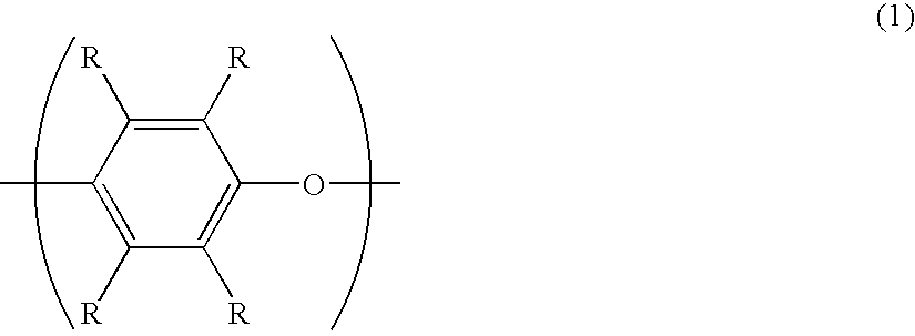
TECHNICAL FIELD [0001] The present invention relates to a relay block comprising a composition which contains a polyamide, a polyphenylene ether and a block copolymer comprising at least one polymer block mainly composed of an aromatic vinyl compound and at least one polymer block mainly composed of a conjugated diene compound and which satisfies a melt volume rate (MVR) of not less than a specific value and a water absorption of not more than a specific value. BACKGROUND ART [0002] Hitherto, polyamide 6,6 resins have been used for relay blocks provided in an engine room of automobiles, but polyamide 6,6 resins have the problem of an increase in dimensional change due to absorption of water, and recently polyamide / polyphenylene ether alloys have been gradually substituted for the polyamide 6,6 resins. For example, JP-A-6-136256 and JP-A-6-141443 disclose relay boxes for automobiles comprising a composition which is composed of polyamide 6,6, polyamide 6, a modified polyphenylene eth...

Claims


Application Information

Patent Timeline
Patent Type & Authority Applications(United States)
IPC IPC(8): C08K5/01C08L53/00C08L53/02C08L71/12C08L77/00C08L93/04
CPCC08G2261/126C08K5/01C08L53/00C08L53/02C08L2205/05C08L71/123C08L77/00C08L93/04C08L71/12C08L2666/14C08L2666/20C08L2666/02C08L2666/24C08L2666/04
Inventor MIYOSHI, TAKAAKIKATAYAMA, SHIGEKI
Owner ASAHI KASEI CHEM CORP
Learn More