
Optical film, polarizing plate and liquid crystal display device

a technology of liquid crystal display device and polarizing plate, which is applied in the direction of polarizing elements, instruments, synthetic resin layered products, etc., can solve the problems of insufficient 3d image content and inability to provide high-quality 3d stereoscopic images, and achieve the effect of preventing the phenomenon

Active Publication Date: 2014-02-11
FUJIFILM CORP
View PDF15 Cites 3 Cited by
  • Summary
  • Abstract
  • Description
  • Claims
  • Application Information

AI Technical Summary

Benefits of technology

This solution effectively prevents misalignment and crosstalk in 3D switchable image display panels by minimizing dimensional changes with temperature, thereby enhancing the quality of 3D display performance.

Problems solved by technology

In the meantime, the contents of 3D images for flat panel displays have not been sufficient yet.
Further, in the flat panel display field in which high definition has recently progressed, it has been currently thought that it is impossible to provide a high-quality 3D stereoscopic image while maintaining a high definition on a flat panel display in the related art by any mode other than these two modes.

Method used


Image

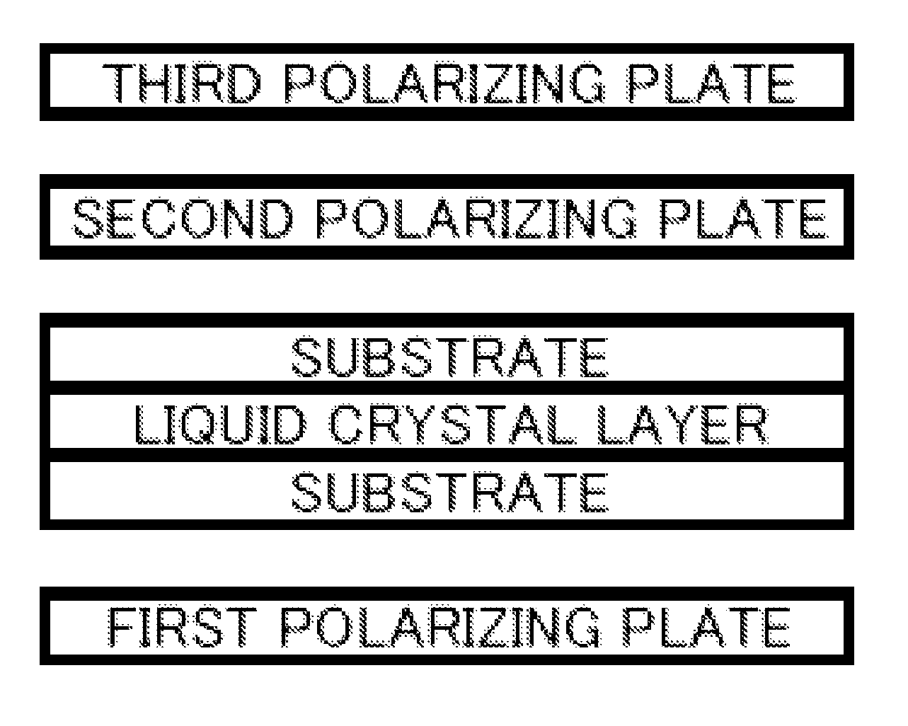
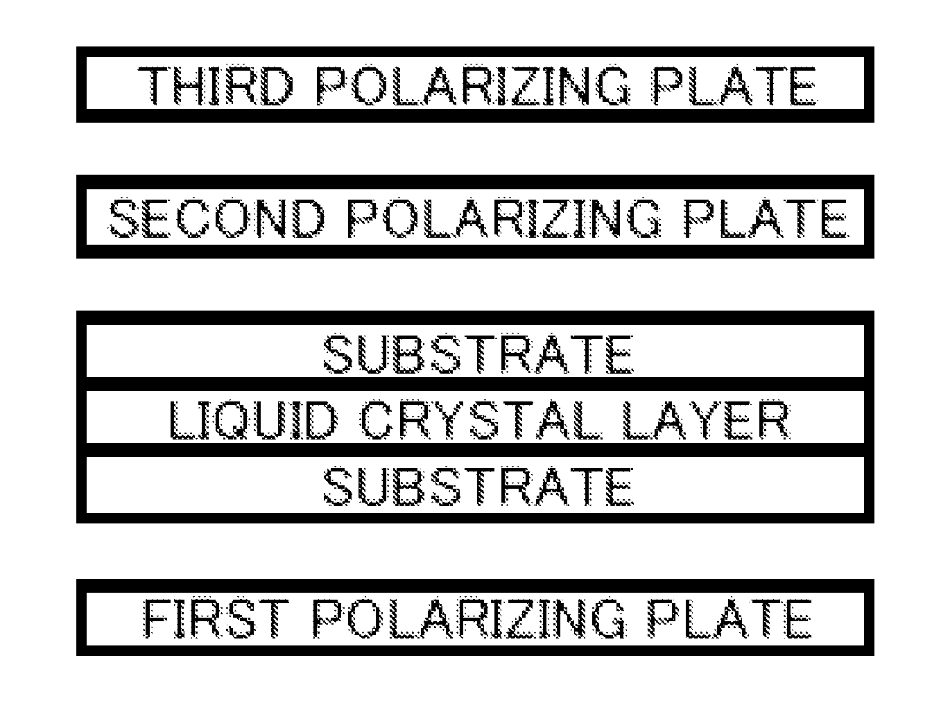
  • Optical film, polarizing plate and liquid crystal display device
  • Optical film, polarizing plate and liquid crystal display device
  • Optical film, polarizing plate and liquid crystal display device

Examples


example

[0294]Hereinafter, the present invention will be described in more detail with reference to Examples. Materials, reagents, material amounts and proportions thereof, operations and the like shown in the following Examples may be appropriately changed as long as the spirit of the present invention is not deviated therefrom. Accordingly, the scope of the present invention is not limited to the following specific Examples.

[0295][Preparation Example of Support Film]

[0296](Support Film 1)

[0297]A dope is prepared by introducing 100 parts by mass of a cellulose acetate having a degree of substitution of 2.86 (the viscosity average polymerization degree is 300, the degree of substitution of acetyl groups at 6-position is 0.89, the acetone extraction portion is 7% by mass, the molecular weight ratio of mass average molecular weight / number average molecular weight is 2.3, the water content is 0.2% by mass, the viscosity in a 6 mass % dichloromethane solution is 305 mPa·s, the residual acetic a...


PUM

PropertyMeasurementUnit
elastic modulusaaaaaaaaaa
angleaaaaaaaaaa
angleaaaaaaaaaa

Abstract

There is provided an optical film having a small size change with a temperature change of a support of a pattern retardation film. An optical film includes: a support comprising a polymer having a moisture absorptivity of 0.5% or more; a first retardation region and a second retardation region, in which birefringence thereof is mutually different; and an optically anisotropic layer in which the first retardation region and the second retardation region are alternately patterned for every one line.

Description

CROSS-REFERENCE TO RELATED APPLICATIONS[0001]The present invention is a 35 U.S.C. 371 National Stage Entry of PCT / JP2011 / 053578, filed Feb. 18, 2011, which claims priority from Japanese Patent Application No. 2010-035462, filed on Feb. 19, 2010, the contents of which are herein incorporated by reference in their entirety.TECHNICAL FIELD[0002]The present invention relates to an optical film, a polarizing plate and a liquid crystal display device. More specifically, the present invention relates to a 2D / 3D switchable image display panel and a 2D / 3D switchable image display system, which may display stereoscopic images and 2-dimensional images, and a pattern retardation film used in the image display panel.BACKGROUND ART[0003]In the 3D stereoscopic image display field in which a projected image is stereoscopically viewed as if the image is emerging and a powerful image may be enjoyed, recently, as 3D movies have been rapidly adopted by the general public, the 3D stereoscopic image disp...

Claims


Application Information

Patent Timeline
Patent Type & Authority Patents(United States)
IPC IPC(8): G02F1/1347G02B30/25
CPCH04N13/0434G02B5/3033H04N13/337G02B5/30G02F1/13363
Inventor YANAI, YUJIROSATA, HIROAKINAKAYAMA, HAJIMESASADA, YASUYUKI
Owner FUJIFILM CORP
Learn More