Ion Milling Apparatus and Sample Holder
- Summary
- Abstract
- Description
- Claims
- Application Information
AI Technical Summary
Benefits of technology
Problems solved by technology
Method used
Image

Examples
first embodiment
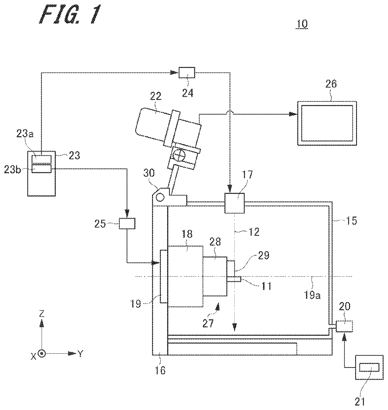
[0063]FIG. 1 is a schematic view of an ion milling apparatus associated with a first embodiment of the present invention, illustrating one example of the configuration of the ion milling apparatus. This ion milling apparatus, indicated by reference numeral 10, is used to produce a sample which is either observed, for example, with a scanning electron microscope or a transmission electron microscope or analyzed by an analytical instrument such as an electron probe microanalyzer or an Auger microscope. The ion milling apparatus 10 mills a sample 11 into a shape adapted for observation with a scanning electron microscope or a transmission electron microscope by directing an ion beam 12 at the sample 11 that is to be milled.
[0064]As shown in FIG. 1, the ion milling apparatus 10 has a vacuum chamber 15, a sample stage pull-out mechanism 16, an ion source 17, a sample stage 18, a rotational mechanism 19, an exhaust portion 20, an exhaust control portion 21, a camera 22, a controller 23, a...
second embodiment
[0094]FIG. 9 is a schematic side elevation showing main portions of an ion milling apparatus associated with a second embodiment of the present invention. FIG. 10 is a schematic front elevation showing main portions of the ion milling apparatus of FIG. 9.
[0095]As shown in FIGS. 9 and 10, the sample holder 27 has a pair of clamp members 41, 42 in addition to the aforementioned shield member 29 and sample locking member 31. The clamp members 41 and 42 are equivalent to first and second clamp members, respectively. The shield member 29 is secured to the clamp member 41 with a screw 43. The sample locking member 31 is secured to the clamp member 42 with a screw 44. The shield member 29 has an internally threaded portion (not shown) with which an externally threaded portion of the screw 43 threadedly engages. The clamp member 41 has a stepped hole (not shown) in which the head and shank of the screw 43 can be inserted. Similarly, the sample locking member 31 has an internally threaded po...
third embodiment
[0100]FIG. 13 is a schematic side elevation showing main portions of an ion milling apparatus associated with a third embodiment of the present invention. As shown in FIG. 13, the sample locking member 31 has support portions 33a, 33b on its opposite ends in the Y direction. The support portion 33a lies at the front end of the sample locking member 31 and is formed by the first surface 34 and a second surface 35a. The support portion 33b lies at the rear end of the sample locking member 31 and is formed by the first surface 34 and a second surface 35b. The second surface 35a tilts at a given angle θ1 relative to the first surface 34. The second surface 35b makes a second given angle of θ2 to the first surface 34. The given angle θ1 is less than 90° and greater than 0°. Preferably, the given angle θ1 is an acute angle, more preferably less than 60°, still more preferably less than 55°, yet more preferably less than 45°. These principles also apply to the second given angle θ2. In the...
PUM
 Abstract
Description
Claims
Application Information
 - R&D
- Intellectual Property
- Life Sciences
- Materials
- Tech Scout
- Unparalleled Data Quality
- Higher Quality Content
- 60% Fewer Hallucinations
Browse by: Latest US Patents, China's latest patents, Technical Efficacy Thesaurus, Application Domain, Technology Topic, Popular Technical Reports.
© 2025 PatSnap. All rights reserved.Legal|Privacy policy|Modern Slavery Act Transparency Statement|Sitemap|About US| Contact US: help@patsnap.com