Image processing apparatus, image processing method, inspection apparatus, and non-transitory computer readable recording medium

a technology of image processing and inspection apparatus, which is applied in the direction of image enhancement, 2d-image generation, instruments, etc., can solve problems such as defects, and achieve the effect of efficient design of inspection image regions

Pending Publication Date: 2022-03-17
DAINIPPON SCREEN MTG CO LTD
View PDF0 Cites 2 Cited by
  • Summary
  • Abstract
  • Description
  • Claims
  • Application Information

AI Technical Summary

Benefits of technology

[0016]Therefore, an object of the present invention is to provide a technique capable of efficiently designating an inspection image region for a captured image related to an inspection object.

Problems solved by technology

Conventionally, for an inspection object such as a component having a three-dimensional shape, a defect has been found by visual inspection in which a person looks at the inspection object from various angles.

Method used


Image

  • Image processing apparatus, image processing method, inspection apparatus, and non-transitory computer readable recording medium
  • Image processing apparatus, image processing method, inspection apparatus, and non-transitory computer readable recording medium
  • Image processing apparatus, image processing method, inspection apparatus, and non-transitory computer readable recording medium

Examples


Embodiment Construction

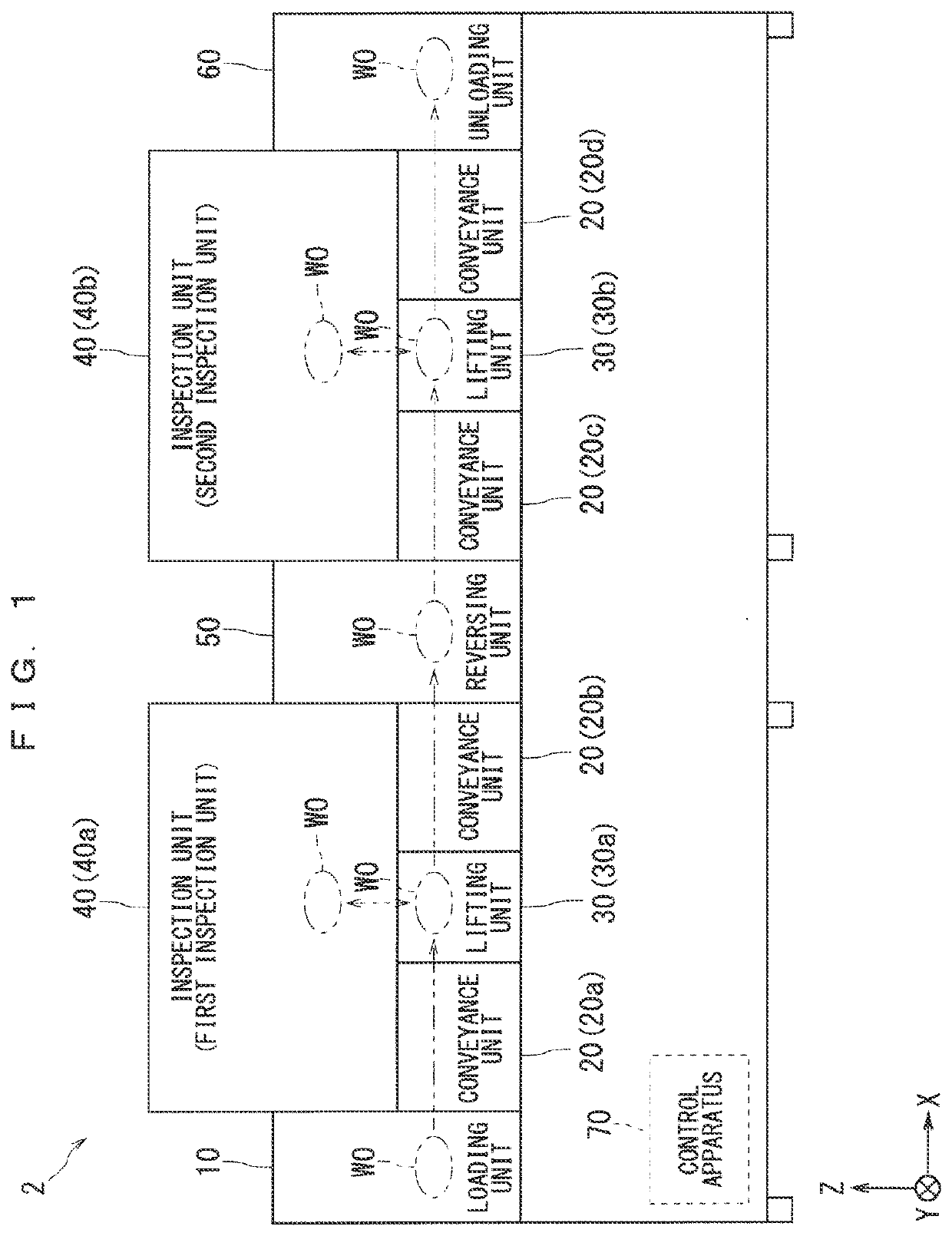
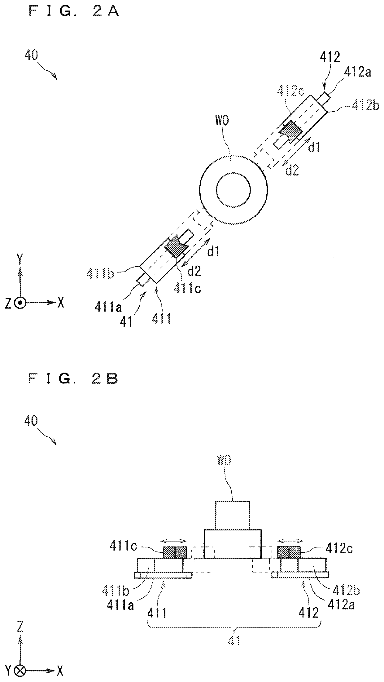
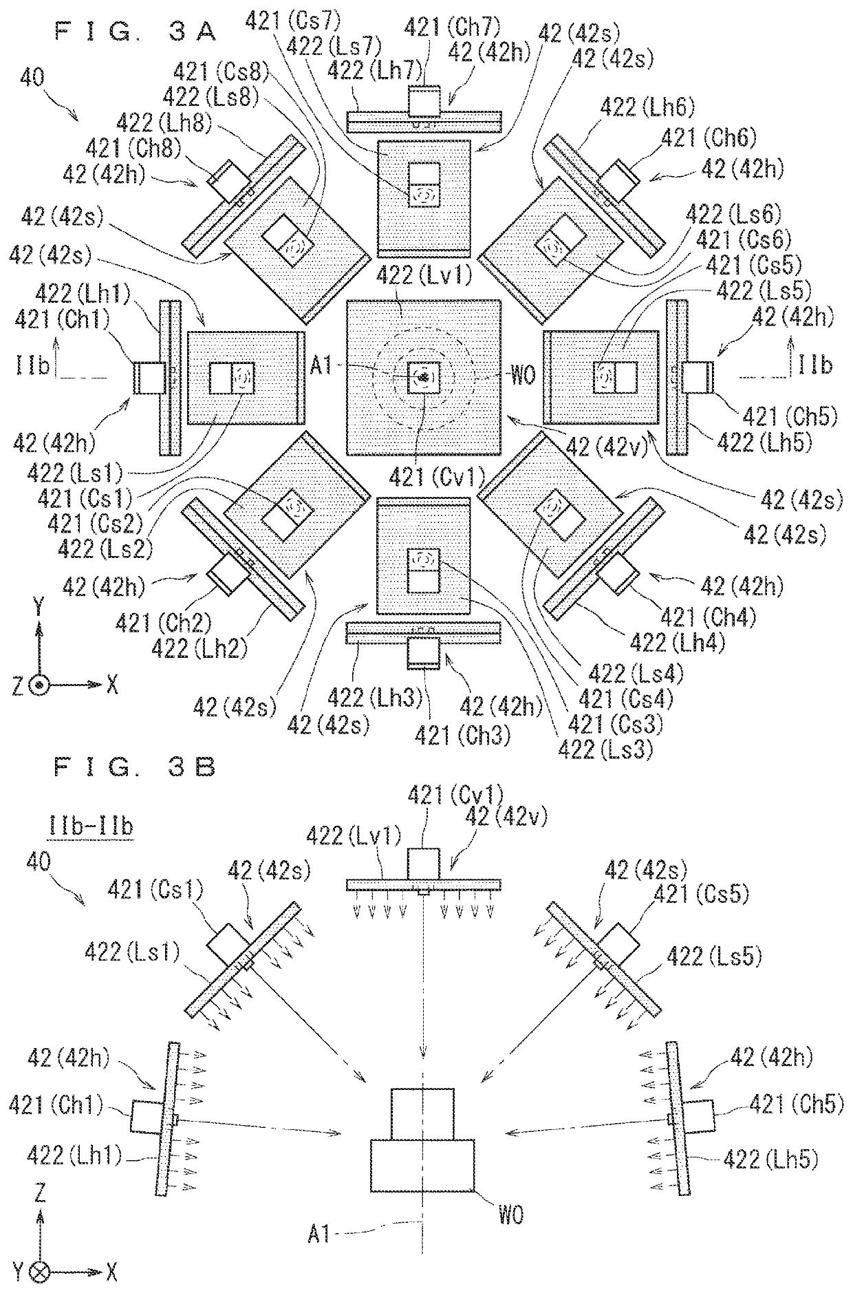
[0045]Hereinafter, each of the preferred embodiments of the present invention will be described with reference to the accompanying drawings. The components described in each embodiment are merely examples, and are not intended to limit the scope of the present invention only to them. The drawings are only schematically shown. In the drawings, the dimensions and number of parts may be shown to be exaggerated or simplified as necessary for easy understanding. In addition, in the drawings, parts having similar configurations and functions are denoted by the same reference numerals, and redundant description is omitted as appropriate. In FIGS. 1 to 3B, 5, 18, and 19, a right-handed XYZ coordinate system is assigned. In this XYZ coordinate system, a direction in which an inspection object (also referred to as a workpiece) W0 is conveyed along a horizontal direction in the inspection apparatus 2 in FIG. 1 is a +X direction, a direction orthogonal to the +X direction along a horizontal pla...


PUM


Abstract

A first acquisition unit acquires three-dimensional model information related to a three-dimensional model of an inspection object and inspection region information related to an inspection region in the three-dimensional model. A second acquisition unit acquires position attitude information regarding a position and an attitude of an imaging unit and the inspection object in an inspection apparatus. A designation unit creates region designation information for designating an inspection image region corresponding to the inspection region for a captured image that can be acquired by imaging of the inspection object by the imaging unit based on the three-dimensional model information, the inspection region information, and the position attitude information.

Description

BACKGROUND OF THE INVENTIONField of the Invention[0001]The present invention relates to an image processing apparatus, an image processing method, an inspection apparatus, and a non-transitory computer readable recording medium.Description of the Background Art[0002]Conventionally, for an inspection object such as a component having a three-dimensional shape, a defect has been found by visual inspection in which a person looks at the inspection object from various angles. However, an inspection apparatus that automatically inspects the inspection object for the purpose of reducing personnel and securing a quality level is considered.[0003]In such an inspection apparatus, for example, a region (also referred to as an inspection image region) in which a portion to be inspected in the inspection object is captured can be designated by the user on the captured image displayed on the screen (For example, Japanese Patent Application Laid-Open No. 2015-21764).SUMMARY OF THE INVENTION[0004]...

Claims


Application Information

Patent Timeline
Patent Type & Authority Applications(United States)
IPC IPC(8): G06T7/00G06T17/00G06K9/00G06K9/20G06T11/00
CPCG06T7/0002G06T17/00G06T2207/20092G06K9/2054G06T11/00G06K9/00214G06T7/11G06T7/33G06T7/0004G06T2207/10028G06T2207/20021G06T2207/30164G06V20/653G06V10/22
Inventor ONISHI, HIROYUKI
Owner DAINIPPON SCREEN MTG CO LTD
Why Eureka
Try Eureka