
Head up display system

a display system and display light technology, applied in the direction of diffusing elements, optics, instruments, etc., can solve the problems of reducing the performance of the display light, reducing the size of the optical component, and glare can be annoying or dangerous to the driver, so as to reduce the intensity of the display light. , the effect of reducing the intensity of the display ligh

Active Publication Date: 2022-04-21
CONTINENTAL AUTOMOTIVE SYST INC
View PDF1 Cites 0 Cited by
  • Summary
  • Abstract
  • Description
  • Claims
  • Application Information

AI Technical Summary

Benefits of technology

The present invention provides a head up display system for a vehicle that reduces glare without changing the position or size of optical components. The system includes a picture generating unit, a tilted mirror, and an intermediate image plane. A pair of prisms is used to eliminate or mitigate undesired light beams emanating from the intermediate image plane. This prevents external light, like sunlight, reflected by the system from reaching the vehicle operator's view without reducing the intensity of the display light. The technical effect is improved visibility and reduced glare for the driver.

Problems solved by technology

This may cause glare to the vehicle operator or otherwise prevent the vehicle operator paying attention to the road ahead of the vehicle.
However, if sunlight hits the i-plane directly or via the HUD optics, there is a chance that a portion of the sunlight is reflected by the PGU mirror(s), back to the driver's eyes.
As already mentioned, glare can be annoying or even dangerous to the driver.
Reducing the size of optical components typically means reducing the performance of the HUD, specifically the perceived image size and / or the size of the area from which the image can be seen.
Further, predicting glare conditions during the design phase of a HUD within a vehicle is time-consuming and imprecise.
Using the described methods to address a glare found after the design phase of the HUD can be a big effort, impacting timing and commercial viability of a project.

Method used


Image

  • Head up display system
  • Head up display system
  • Head up display system

Examples


Embodiment Construction

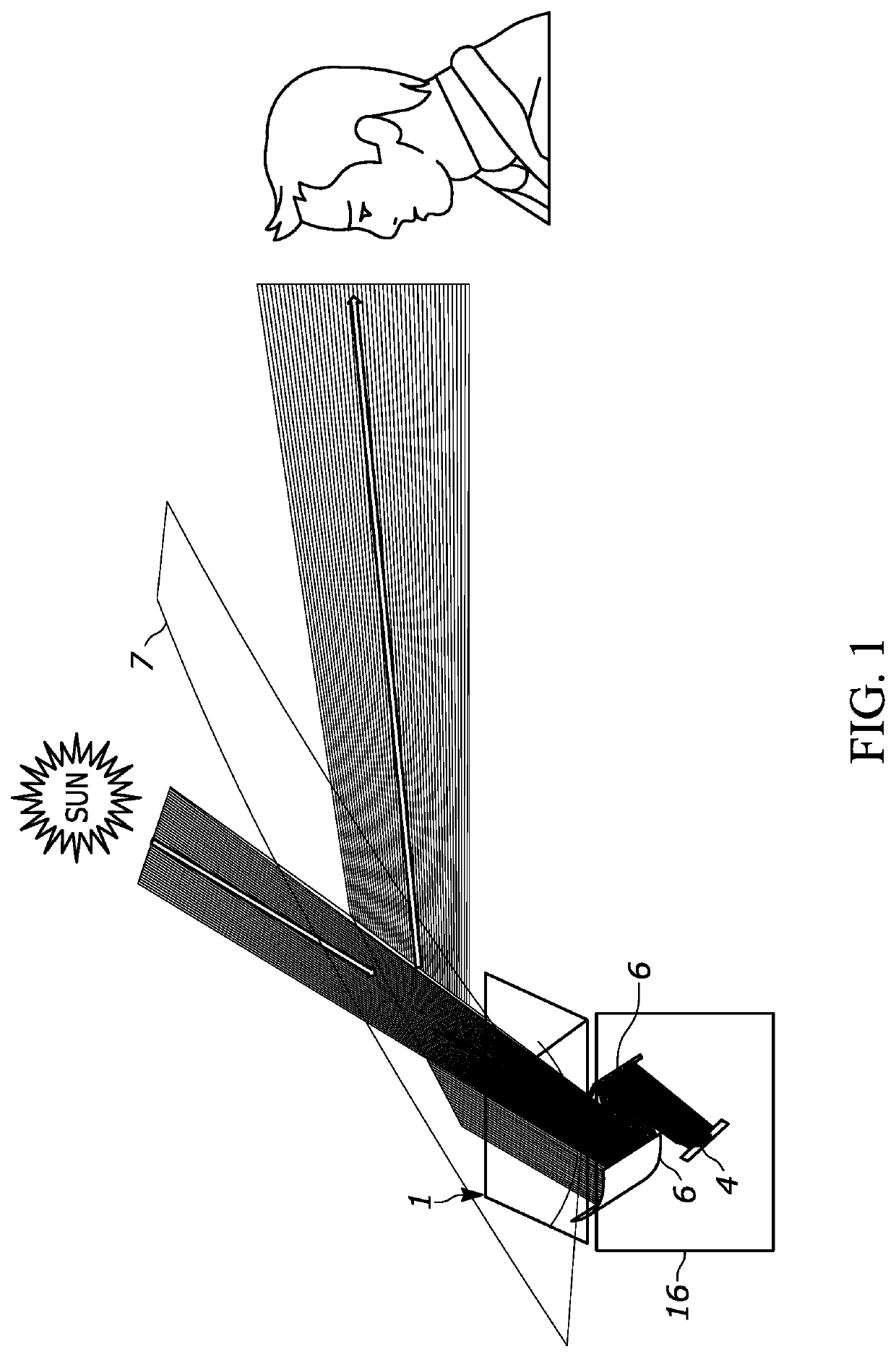
[0060]FIG. 1 shows a side view of a situation in that glare arises due to the sun being at a specific orientation to generate glare in the driver's field of view.

[0061]Sunlight crosses the windshield 7 and enters the HUD system. Via the optical lens and / or mirror arrangement 6, the sunlight hits the diffuser screen 5, diffuses within the diffuser screen 5, hits the tilted mirror 4 in the PGU 2, is reflected back through the diffuser screen 5, and travels toward the driver's eye through the HUD Optics 6, and reflection by the windshield 7.

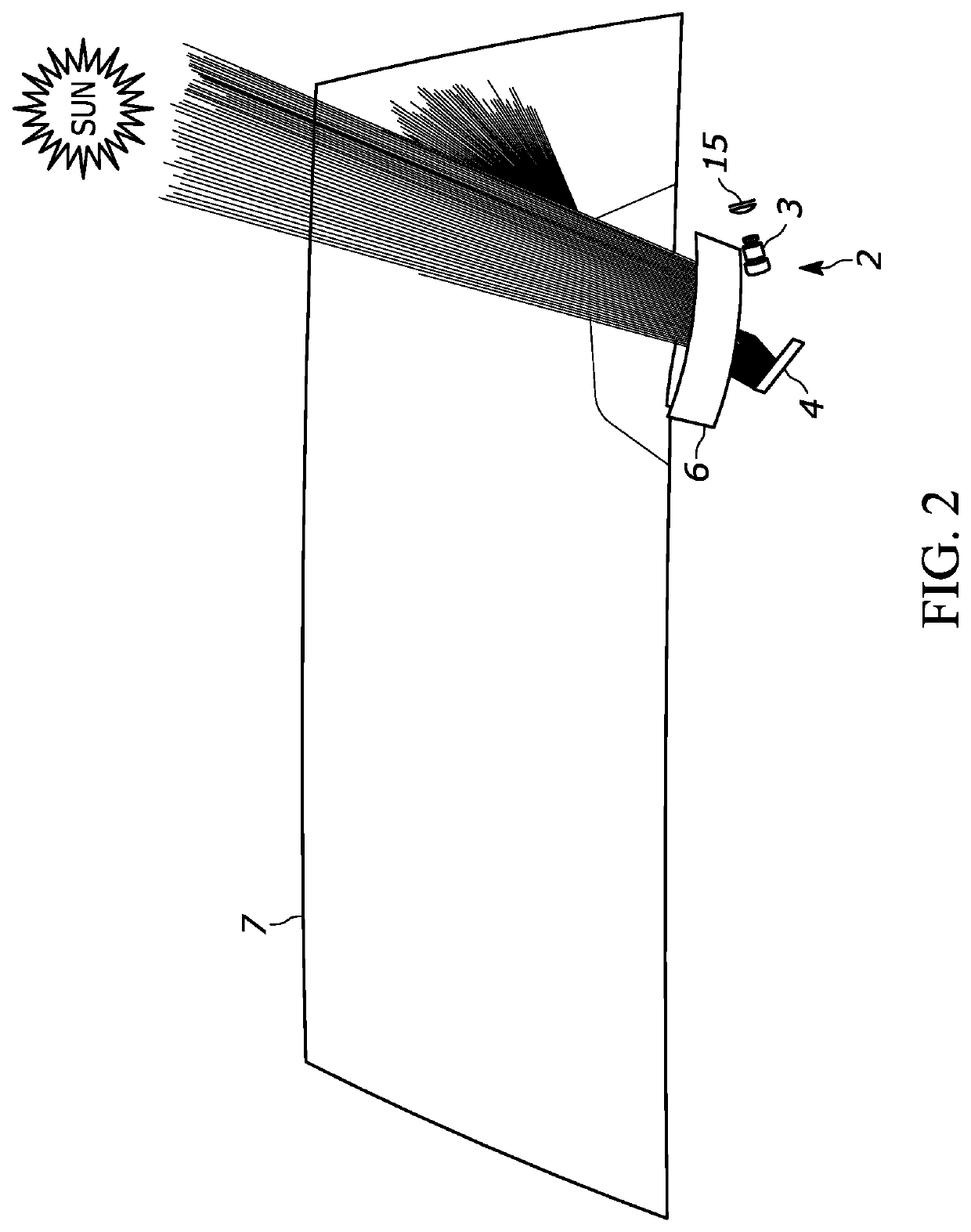
[0062]FIG. 2 depicts a front view of the situation of FIG. 1. In addition to FIG. 1, in FIG. 2 the SLM 15, Spatial Light Modulator, and the picture projection optics 2 guiding the light to the backside of the intermediate image plane 5 via the tilted mirror 4, are shown.

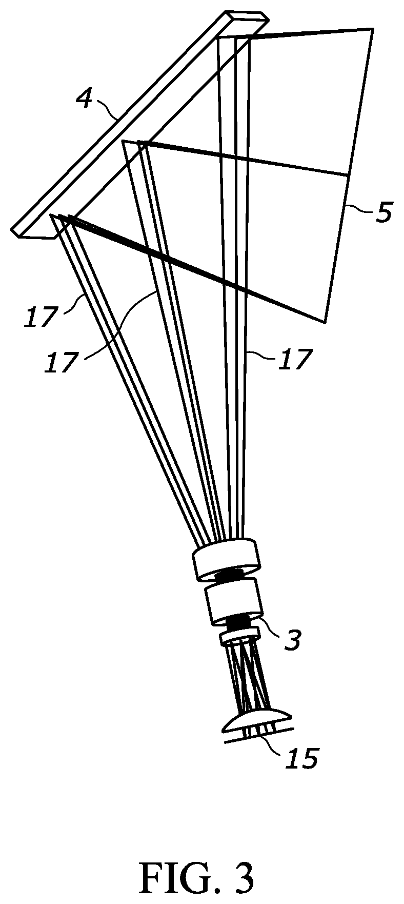
[0063]FIG. 3 shows the details of the picture generation unit 2, PGU, with the desired light forming an intermediate image on the diffuser screen 5.

[0064]The light beams 17 are modul...


PUM


Abstract

The present invention relates to a head up display system, in particular for a motor vehicle, comprising: a picture generating unit having a picture projection optics, a tilted mirror and an intermediate image plane, wherein light from the picture projection optics is deflected by the mirror toward the backside of the intermediate image plane, and an optical lens and / or mirror arrangement for magnifying and / or conveying a picture generated on the intermediate image plane to an optical combiner, wherein a pair of prisms is inserted in the optical path between the tilted mirror and the intermediate image plane to eliminate or mitigate specific light beams emanating from the intermediate image plane and traveling toward the tilted mirror and / or specific light beams emanating from the intermediate image plane already being reflected from the tilted mirror and traveling back toward the intermediate image plane.

Description

BACKGROUND[0001]Embodiments of the invention relate generally to a head up display system for overlaying a generated image on a scene.[0002]It has proven to be very beneficial to project information directly into a driver's field of view by using the windshield as a screen for a display device installed in the dashboard panel. By this, the driver is less distracted and is able to continuously keep his eyes on the road.[0003]In conventional head up display systems (abbreviated as HUD systems) the display device is placed in a recessed part of the dashboard panel, and is thereby concealed from the direct view of the vehicle operator.[0004]An output light beam of the HUD system is reflected by the inner surface of the windshield at such an angle that the displayed image is seen by the vehicle driver, preferably in a manner as if the image were located at some distance ahead of the windshield.[0005]However, in such a HUD system, external light, e.g. sunlight, entering the passenger comp...

Claims


Application Information

Patent Timeline
Patent Type & Authority Applications(United States)
IPC IPC(8): G02B27/01G02B5/04G02B5/00G02B5/02
CPCG02B27/0101G02B5/0273G02B5/003G02B5/04G02B27/0018
Inventor HONG, YOUNGBUECHEL, ANDREASMARTA, BOGDANKNAPP, HEATHER
Owner CONTINENTAL AUTOMOTIVE SYST INC
Learn More