
Vehicular exterior mirror system with blind spot indicator

a technology of exterior mirrors and blind spots, which is applied in the direction of vehicle components, optical viewing, transportation and packaging, etc., can solve the problems of difficult determination and the inability of the driver of the host vehicle to view the turn signal visual indicators, etc., to achieve convenient connection, easy connection, and enhanced assembly process

Active Publication Date: 2022-05-19
MAGNA MIRRORS OF AMERICA INC
View PDF1 Cites 5 Cited by
  • Summary
  • Abstract
  • Description
  • Claims
  • Application Information

AI Technical Summary

Benefits of technology

The patent describes a display device that can be attached to a mirror, such as a turn signal indicator or a blind spot / LCA display, to provide better visibility and safety for the driver. The device includes a baffle that protects the driver from seeing the light source and allows the illumination to be viewed by the targeted viewer. The invention simplifies the assembly process and allows for the integration of the indicator and light baffle into the mirror reflector sub-assembly. Overall, the patent provides a more efficient and effective solution for improving safety and visibility for drivers.

Problems solved by technology

It is known to provide an object in a blind spot detection / LCA system for a vehicle that detects the presence of another vehicle or object in the lane next to the host vehicle, where it may be difficult for the driver of the host vehicle to determine whether or not there is another vehicle or object adjacent to the host vehicle.
It is desirable that such turn signal visual indicators are not readily viewable by the driver of the host vehicle when they are activated.
Somewhat costly and complicated indicator constructions have been contemplated that, when placed behind and supported by the mirror reflective element, attempt to have their projected beam of emitted light directed principally to be viewed by the driver of the host vehicle (or other persons external to the host vehicle for turn signal applications) through the mirror reflective element and shielded from view by other drivers in blind spot alert detection systems (or from the driver of the host vehicle for turn signal applications).

Method used


Image

  • Vehicular exterior mirror system with blind spot indicator
  • Vehicular exterior mirror system with blind spot indicator
  • Vehicular exterior mirror system with blind spot indicator

Examples


Embodiment Construction

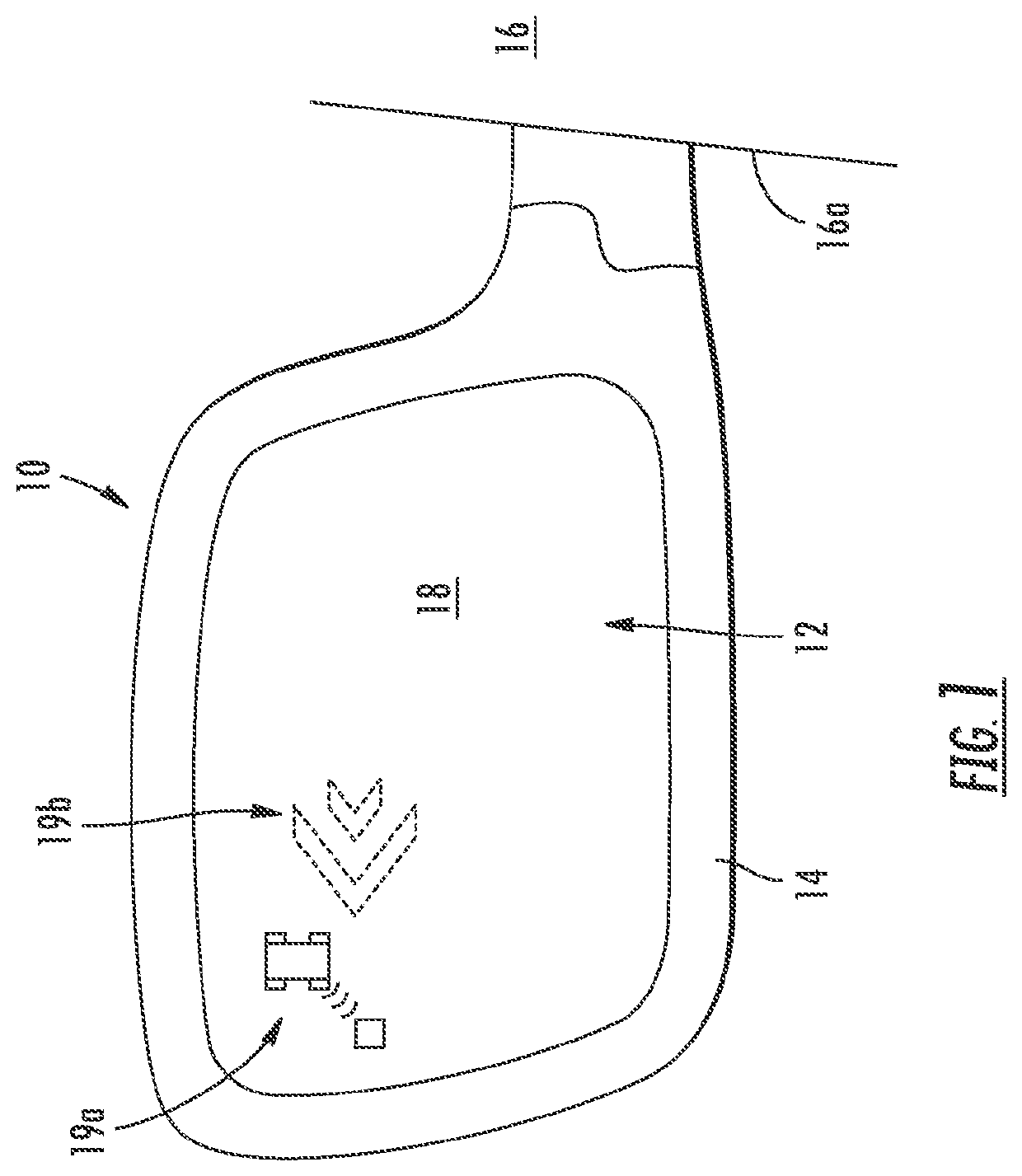
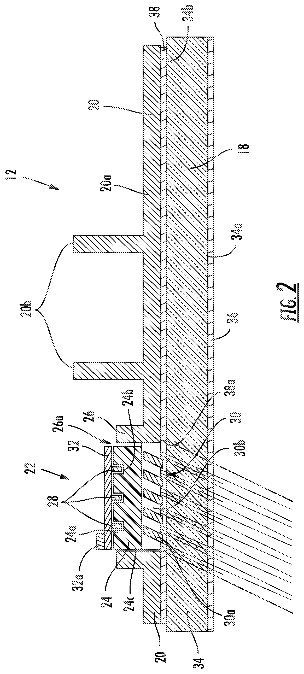
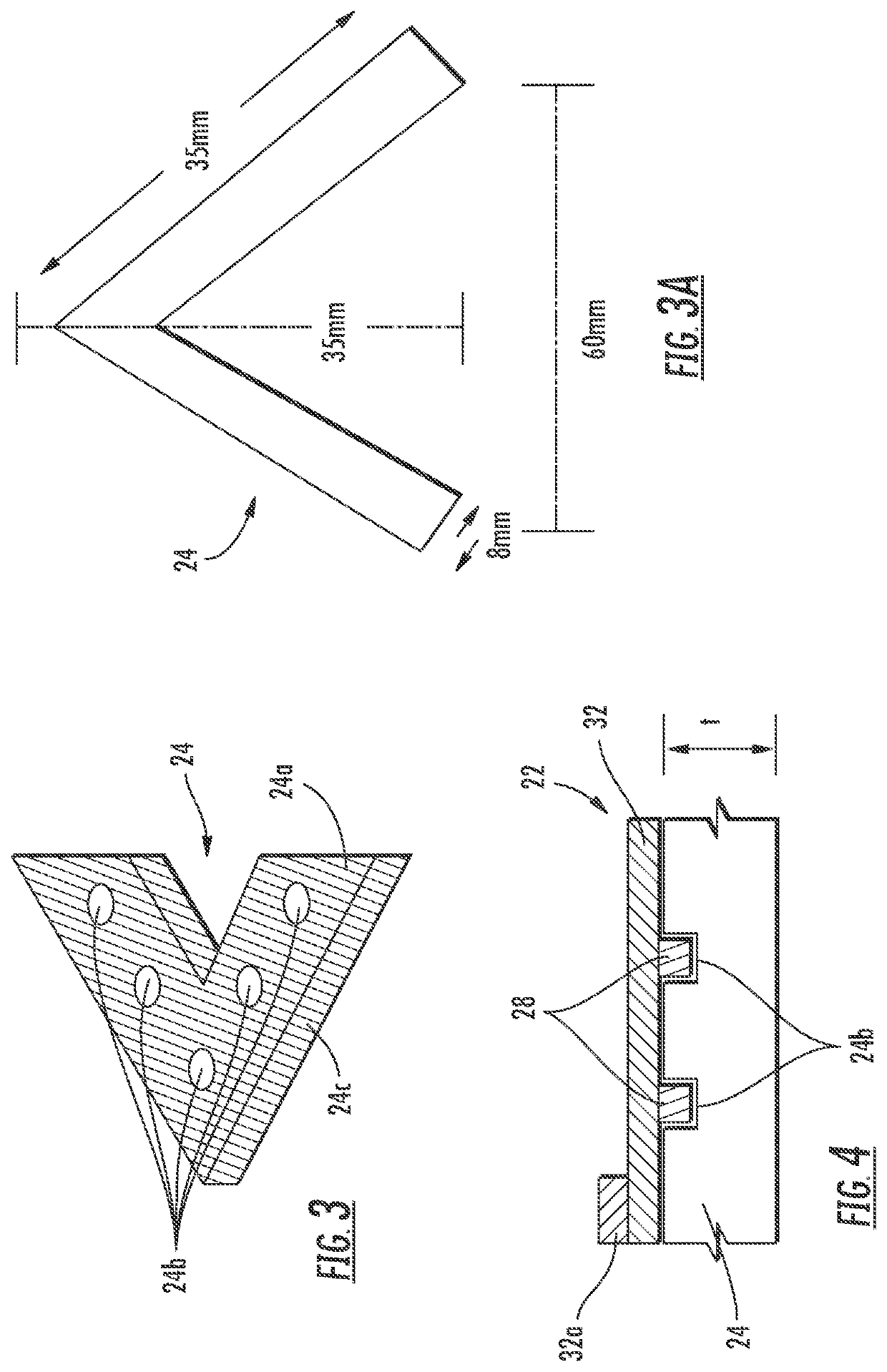
[0063]Referring now to the drawings and the illustrative embodiments depicted therein, an exterior rearview mirror assembly 10 for a vehicle includes a mirror reflector sub-assembly 12 and a mirror shell or casing 14 (FIG. 1). Mirror assembly 10 is mounted at the side 16a of a host or subject vehicle 16. As shown in FIG. 2, mirror reflector sub-assembly 12 includes a mirror reflective element 18 and a mirror reflector carrier or back plate 20 attached to or mounted to or adhered to a rear surface 18a of mirror reflective element 18. Mirror assembly 10 includes an indicator or display element or device or signal indication module 22 that is disposed at back plate 20 and behind reflective element 18, and that is operable to provide a display or indication at the reflective element for viewing the display or indication through the mirror reflective element. Signal indication module 22 includes a transparent or translucent polymeric block or element or indicating light source or element...


PUM


Abstract

An exterior rearview mirror system for a vehicle includes an exterior mirror assembly having a skull-cap mirror shell that includes an inboard wall that faces generally toward an exterior side of the vehicle and that is viewable by a driver of the vehicle. A multi-stage blind spot indicator is disposed at an aperture established at the inboard wall of the skull-cap mirror shell. An illumination source of the blind spot indicator is activated to illuminate the multi-stage blind spot indicator responsive to an electronic blind spot monitoring system of the vehicle detecting another vehicle that is approaching or overtaking the equipped vehicle. Illumination of the multi-stage blind spot indicator by activation of the illumination source is readily viewable by the driver of the equipped vehicle and is generally not viewable by a driver of another vehicle traveling in front of or approaching from in front of the equipped vehicle.

Description

CROSS REFERENCE TO RELATED APPLICATIONS[0001]The present application is a continuation of U.S. patent application Ser. No. 16 / 819,693, filed Mar. 16, 2020, now U.S. Pat. No. 11,242,009, which is a continuation of U.S. patent application Ser. No. 15 / 083,895, filed Mar. 29, 2016, now U.S. Pat. No. 10,589,686, which is a continuation of U.S. patent application Ser. No. 14 / 714,762, filed May 18, 2015, now U.S. Pat. No. 9,302,624, which is a continuation of U.S. patent application Ser. No. 13 / 919,489, filed Jun. 17, 2013, now U.S. Pat. No. 9,035,754, which is a continuation of U.S. patent application Ser. No. 13 / 572,045, filed Aug. 10, 2012, now U.S. Pat. No. 8,466,779, which is a continuation of U.S. patent application Ser. No. 13 / 290,644, filed Nov. 7, 2011, now U.S. Pat. No. 8,242,896, which is a continuation of U.S. patent application Ser. No. 12 / 446,507, filed Apr. 21, 2009, now U.S. Pat. No. 8,058,977, which is a 371 national phase application of PCT Application No. PCT / US07 / 82099,...

Claims


Application Information

Patent Timeline
Patent Type & Authority Applications(United States)
IPC IPC(8): B60R1/12B60R1/06B60R1/062B60R1/08
CPCB60R1/1207B60R1/06B60R2001/1215B60R1/062B60R1/08B60R1/0602
Inventor LYNAM, NIALL R.
Owner MAGNA MIRRORS OF AMERICA INC
Learn More