
Parallel gripper with adaptive clamping surfaces

a technology of adaptive clamping and parallel gripper, which is applied in the direction of manipulators, gripping heads, chemistry apparatus and processes, etc., can solve the problem of less reliable robust gripping of items with short edges

Pending Publication Date: 2022-06-09
TECAN TRADING AG
View PDF0 Cites 1 Cited by
  • Summary
  • Abstract
  • Description
  • Claims
  • Application Information

AI Technical Summary

Benefits of technology

The invention is a clamp that uses a strip of sheet metal or stiff wire to provide reliable self-alignment and prevent rotation. It is designed to be compact and easy to use with affordable components. The clamp can rotate within a limited range, making it ideal for applications where alignment needs to be maintained.

Problems solved by technology

It has been found that robust gripping of items with short edges is less reliable.

Method used


Image

  • Parallel gripper with adaptive clamping surfaces
  • Parallel gripper with adaptive clamping surfaces
  • Parallel gripper with adaptive clamping surfaces

Examples


Embodiment Construction

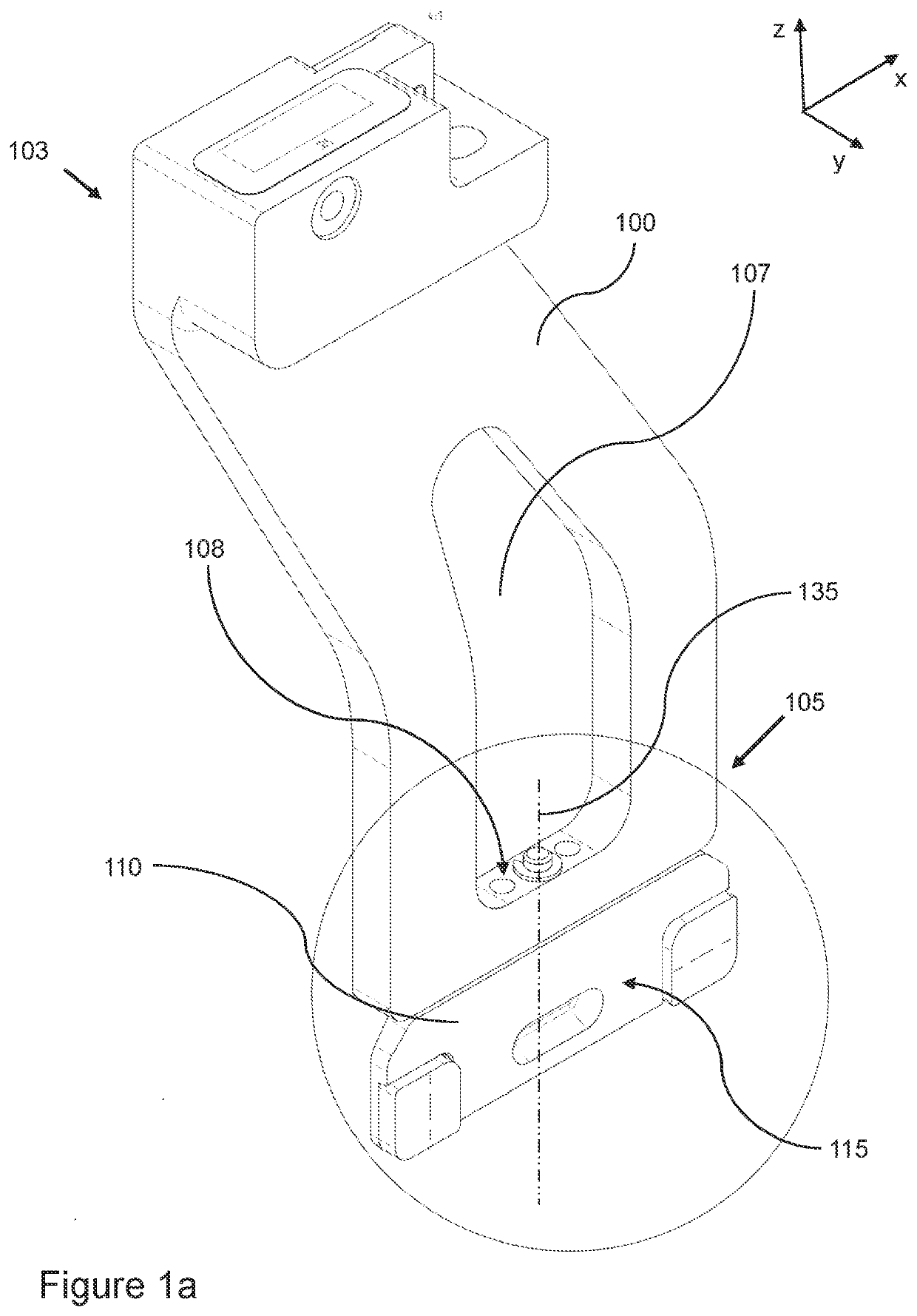
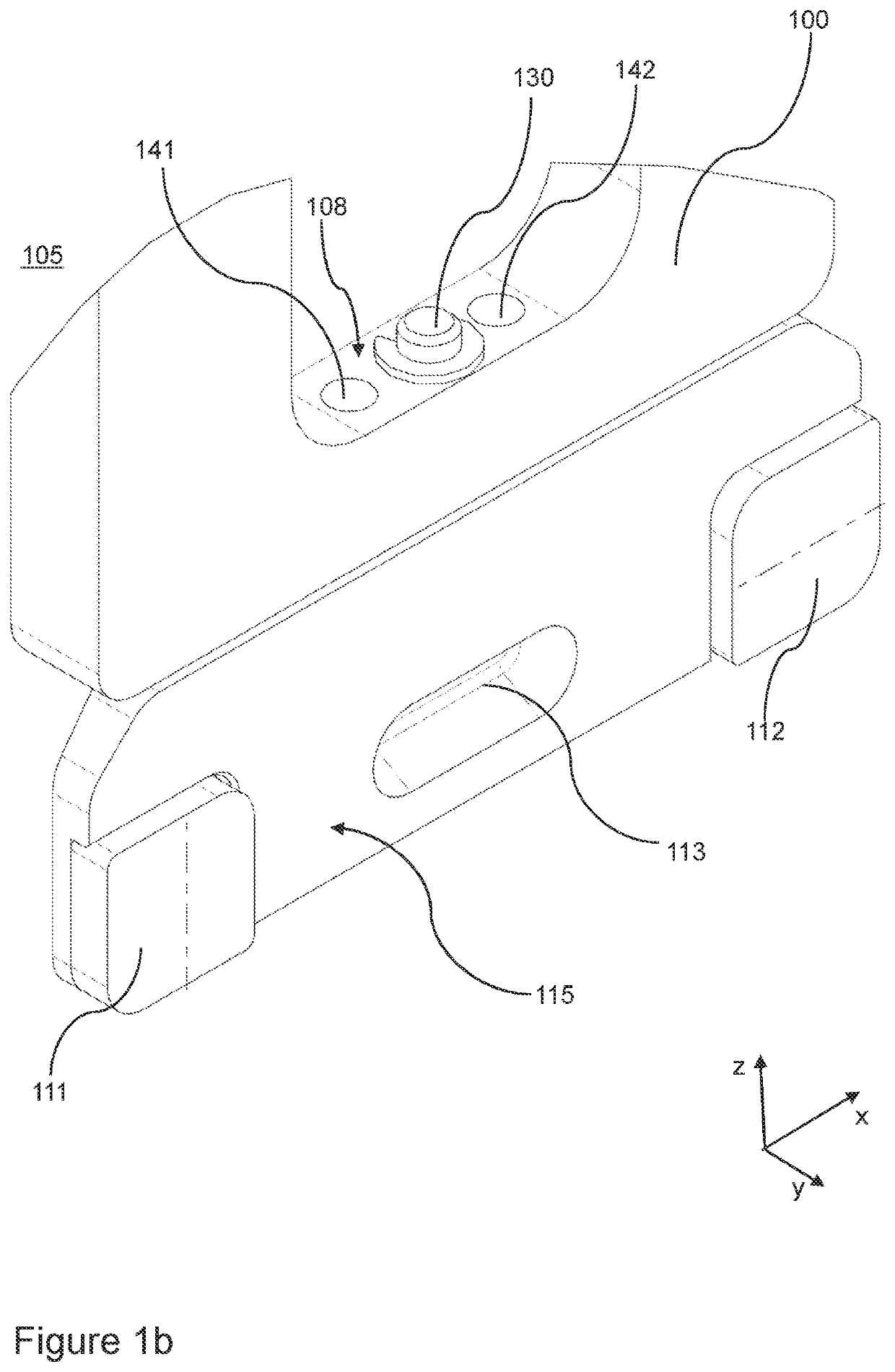
[0027]FIG. 1a shows an example of a gripper finger 100 according to the invention, which in use forms a first finger of a parallel gripper for picking up and depositing items of labware. An upper section 103 of the finger is provided with to an opening for receiving a holding mandrel of a gripper jaw that is mounted on a linear guide, such that the finger 100 can be attached to and detached from the moveable jaw in a manner such as described in U.S. Pat. No. 8,602,470. Other methods of attaching the finger to a parallel gripper are also possible.

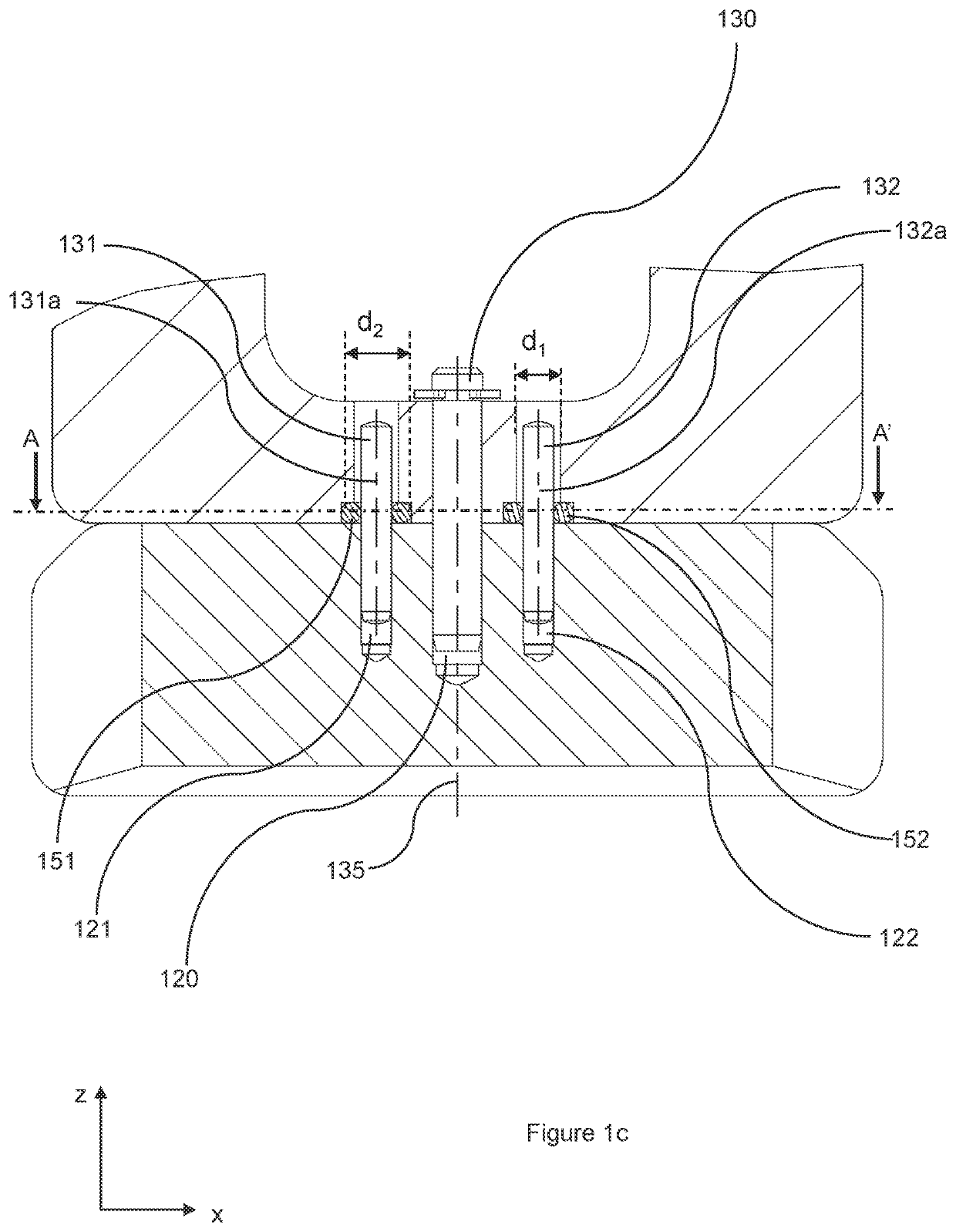
[0028]A lower section 105 of the finger 100 comprises a clamp 110 having a front face 115 that is moved in a direction of translation y into contact with one side of a labware item. In order to grasp the item, an opposing face of the clamp on a second finger is moved into contact with an opposite side of the labware item. Each clamp is a separate part that is fastened to an underside of the finger via a central mounting hole that extends in ...


PUM


Abstract

The invention relates to an arrangement of a gripper finger and a clamp for use in an automated parallel gripper comprising first and second gripper fingers that are moveable in a direction of translation (y), whereby the clamp is connected to the gripper finger at an underside thereof, so as to be rotational about a vertical axis of rotation (135). The clamp has a front face with a contact surface for engagement with a lateral edge of an item to be gripped and has a default orientation in which the front face is parallel to a lateral direction (x) that is perpendicular to the direction of translation (y) and to the vertical rotation axis (135). The arrangement is additionally provided with a self-alignment feature which comprises first and second biasing mechanisms arranged at either side of the rotation axis (135) in lateral direction (x). Each biasing mechanism has a first part (151, 152) connected to the finger and a second part (131, 132) connected to the clamp and is configured to exert a centering force that urges the first and second parts of each biasing mechanism into alignment with each other. When the clamp is in the default orientation, each biasing mechanism is preloaded to exert an equal moment load on the clamp in the direction of translation (y).

Description

FIELD OF THE INVENTION[0001]The invention relates to a gripper finger of an automated gripper comprising parallel first and second fingers that can be moved towards each other and away from each other for grasping and depositing objects. More specifically, the invention is directed to a gripper finger having a clamping surface that can be used to pick up different items of labware.BACKGROUND ART[0002]A clamp suitable for gripping first and second types of biological sample holder is disclosed in US2015 / 0071820. The clamp has first and second arms able to move relative to each other along a gripping position between a first position of gripping and a first position of releasing. Each arm of the clamp includes a vertically extending groove for receiving the edge of a gel card holder, so as to grip it by squeezing the edges along the gripping direction. Contact surfaces of the arm, at either side of the groove, are used for gripping lateral edges of a microplate.[0003]A further example...

Claims


Application Information

Patent Timeline
Patent Type & Authority Applications(United States)
IPC IPC(8): B25J15/00B25J15/12
CPCB25J15/0028B25J15/12B01L9/00B25J15/0253B25J15/0042
Inventor BRENNWALD, MIRCOHÄFELFINGER, ANDRÉASCHWANDEN, MARCEL
Owner TECAN TRADING AG
Learn More