
Gravity self-locking hook structure

A self-locking, gravity technology, applied in the direction of passenger space, rack configuration, etc., can solve the problems of unfavorable mass production, restrictions, and insufficient convenience

Inactive Publication Date: 2014-12-24
NIFCO TAIWAN
View PDF5 Cites 2 Cited by
  • Summary
  • Abstract
  • Description
  • Claims
  • Application Information

AI Technical Summary

Problems solved by technology

[0005] However, although the existing hook locking device A can use the hook-shaped body A21 to achieve the purpose of being firmly hooked on the article and not easy to fall out, the locking component A3 and the locked component A2 are misaligned by using the main switch lock. Only when the locking state of the hook body A21 can be released, the overall operation will still be subject to certain restrictions, and it cannot provide the user with manual operation, which is not convenient enough, and because the base A1 and the car body use screws (not shown in the figure) The locking method is cumbersome and inconvenient to assemble, plus the base A1 and the locked components
[0006] The overall components of A2 and the locking component A3 are many and complicated, so that the assembly operation is quite time-consuming and costly, and it is not conducive to mass production. This is the direction that people in this industry want to study and improve.

Method used


Image

  • Gravity self-locking hook structure
  • Gravity self-locking hook structure
  • Gravity self-locking hook structure

Examples


Embodiment Construction

[0035] In order to achieve the above-mentioned purpose and effect, the technical means and the structure adopted by the present invention are hereby illustrated in detail with respect to the preferred embodiments of the present invention. Its structure and function are as follows, in order to fully understand.

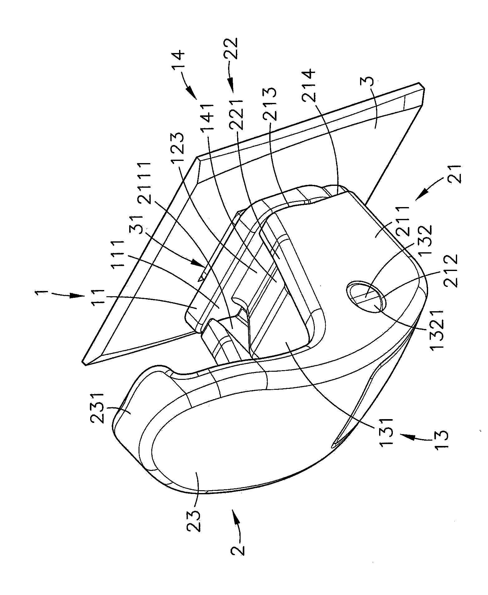
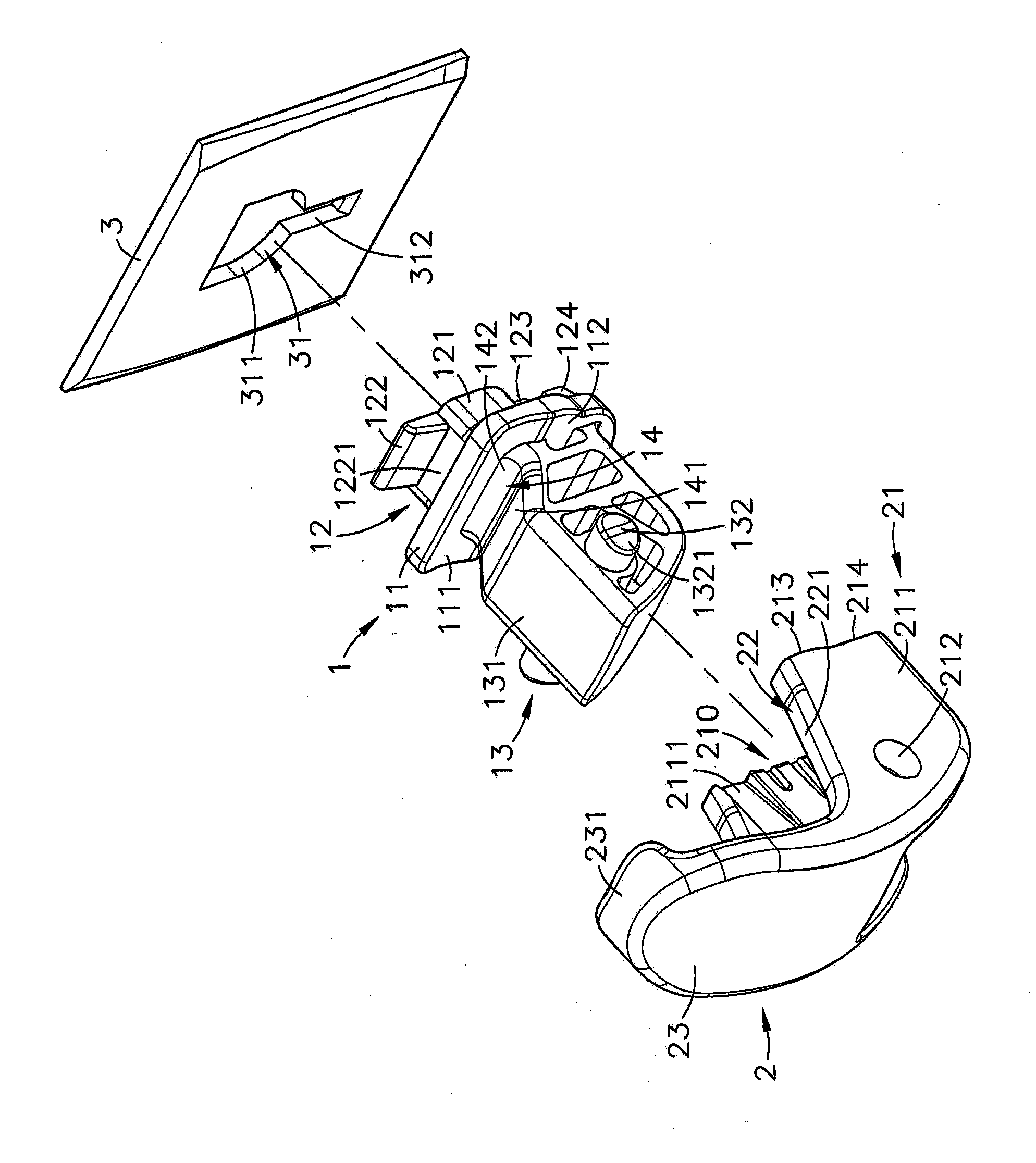
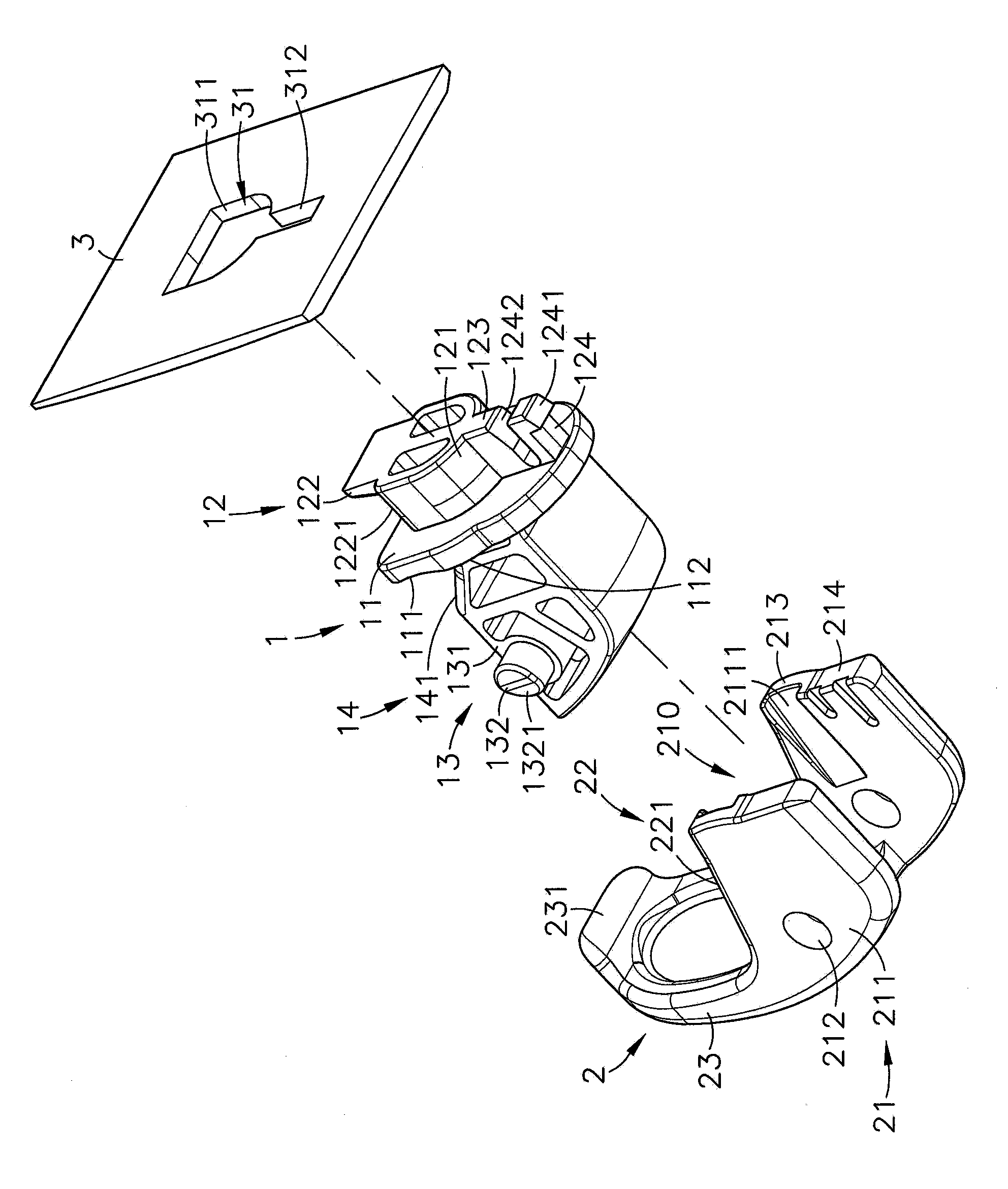
[0036] see figure 1 , figure 2 , image 3 , Figure 4 As shown, they are the three-dimensional appearance diagram, the three-dimensional exploded view, the three-dimensional exploded view and the three-dimensional sectional view of the present invention respectively. It can be clearly seen from the figure that the present invention includes the connecting seat 1, the hooking body 2 and the plate Body 3, so the main components and features of the present invention are described in detail as follows, wherein:

[0037] The connection seat 1 has a vertical base 11, and a positioning part 12 is provided at the rear of one side of the base 11. The positioning part 12 ha...


PUM


Abstract

The invention provides a gravity self-locking hook structure which comprises a connecting base and a hooking body, wherein a positioning part combined with a plate body is arranged at the position of one side of a base which the connecting base is provided with, and a pivoted part is arranged at the position of the other side of the base. A concave part is arranged at the position above the pivoted part adjacent to the base, the hooking body is provided with a connecting part pivoted to the pivoted part, a pushing part is arranged at the position of one side of the connecting part, and a hook part is bent upwards and extends at the position of the other side opposite to the pushing part. When a lifting rope of a hooked body is sleeved with the hooking body, due to the fact that the hooked body is pulled downward on the pushing part of the hooking body due to self weight, the lifting rope slides to the position of the concave part of the connecting base to be hooked and positioned; due to the fact that the gravity center of the hooked body and the axis of the connecting base undergo dislocation, the hooked body can be connected to the hook part through the pushing part to perform rotating displacement towards the plate body with the pivoted part as the axis so as to be automatically locked, and the problem that the lifting rope drops out of the hooking body due to the influence of vibration when a vehicle body runs, so that the hooked body drops and is damaged is solved.

Description

technical field [0001] The invention provides a gravity self-locking hook structure, in particular, a hooking body is pivotally connected to the connecting seat, and a hooking body is provided on one side of the hooking body to be pulled by a lifting rope of the hooked body to make the lifting rope slide and displace The push part is hooked and positioned at the concave part on the connecting seat, and the other side of the hook body is provided with a hook part that can be locked by the push part in conjunction with the pivot part as the axis of rotation and displacement. Background technique [0002] The living standards in today's society are constantly improving, making the quality requirements of clothing, food, housing, transportation and entertainment in daily life more and more high, and the practicality is getting better and better. In terms of transportation, in addition to In addition to locomotives with speed and flexibility, various cars are also becoming more a...

Claims


Application Information

Patent Timeline
IPC IPC(8): B60R7/08
CPCB62J7/08
Inventor 陈荣强
Owner NIFCO TAIWAN
Learn More