
Nose pad assembly for an eyeglass frame

Inactive Publication Date: 2005-03-10
NEGISHI TOHRU
View PDF4 Cites 12 Cited by
  • Summary
  • Abstract
  • Description
  • Claims
  • Application Information

AI Technical Summary

Benefits of technology

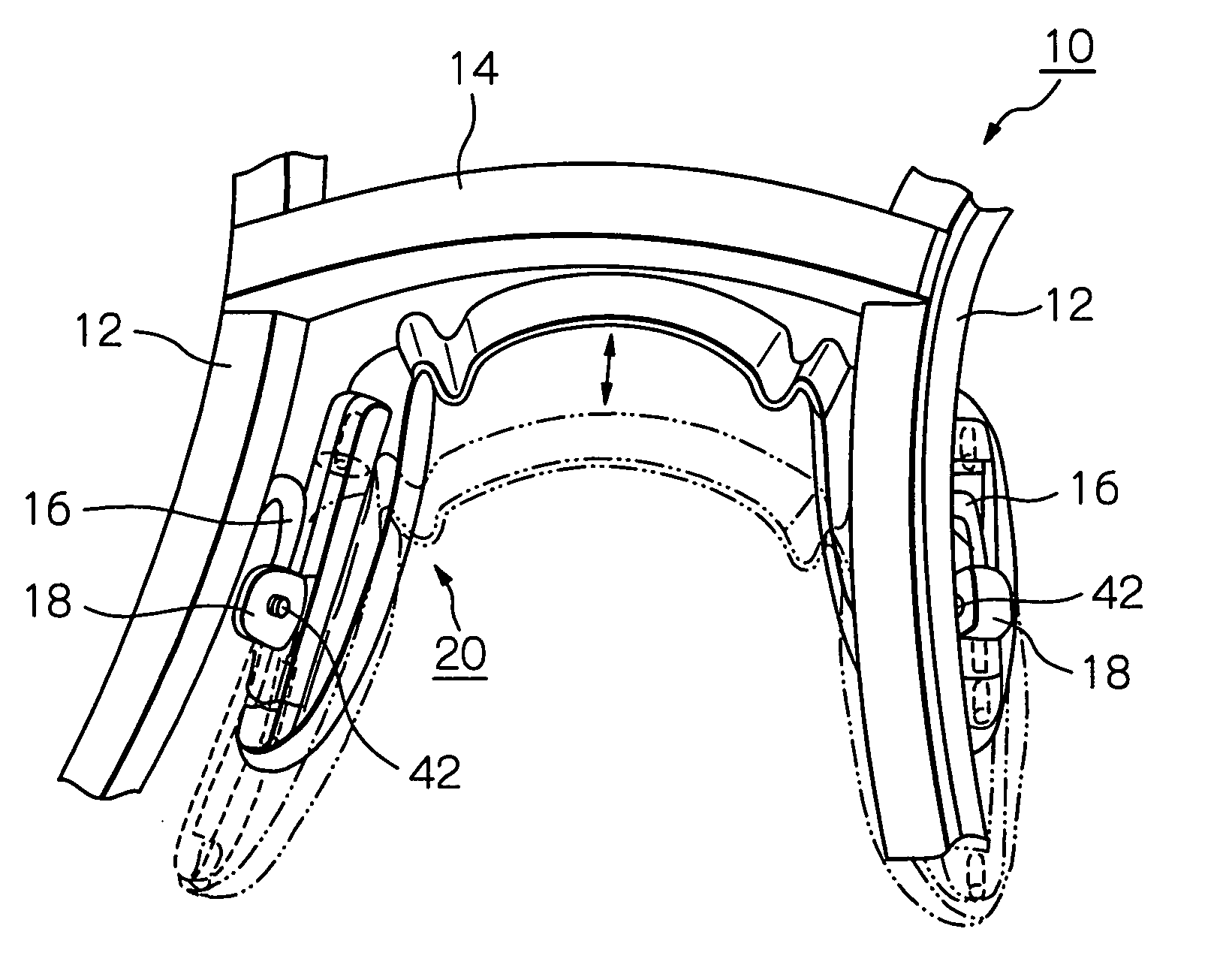
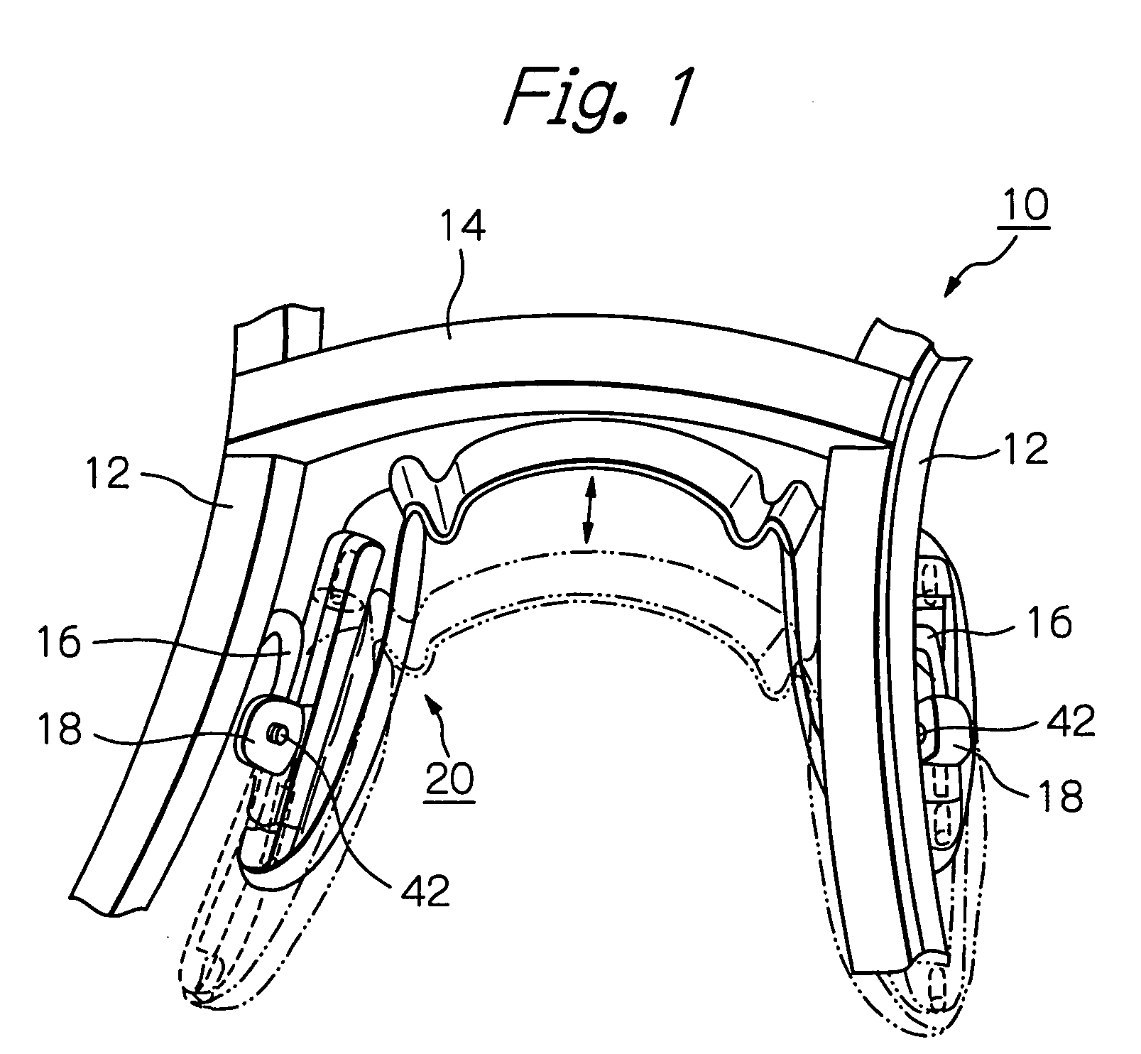
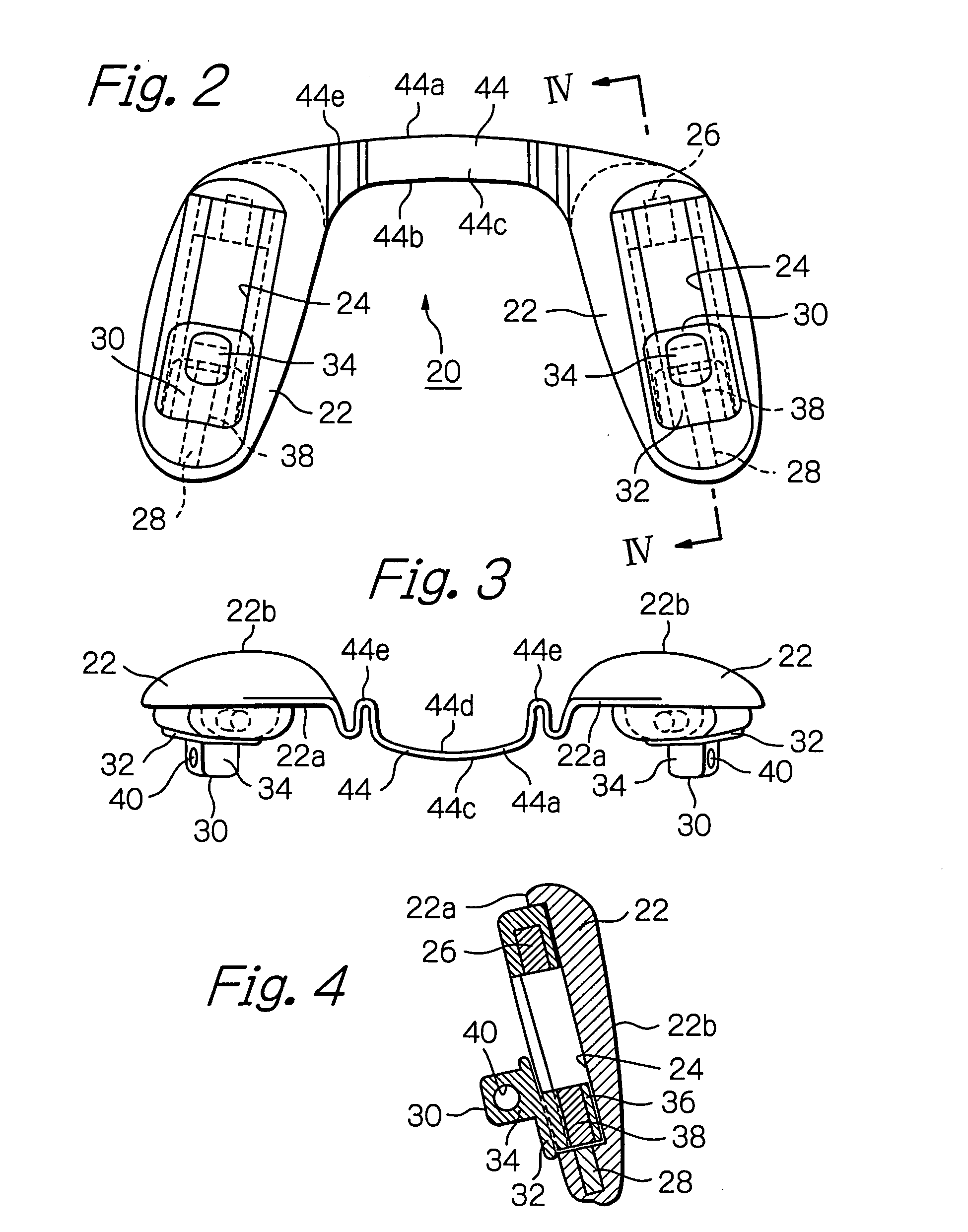
[0007] In one embodiment, the thin bridge member is elongated in a horizontal direction and oriented in an upright position between the nose pads. The bridge member has a horizontally arcuate shape so as not to interfere with the nose of a wearer. The bridge member may have opposite curved or wavy ends. In one embodiment, the curved ends of the bridge member have a S-shape. This arrangement allows rocking of the nose pads in most directions and facilitates adjustment of the nose pads.
[0008] The two nose pads and the bridge member may be of a one-piece construction. Alternatively, the bridge member may be a separate or discrete piece and has opposite ends secured to the nose pads. A single horizontal pin may be employed to secure the bridge member to each of the nose pads. In such a case, the angular position of the nose pads can be varied by rotating the nose pads about the respective horizontal pins. The bridge member may also have elongated slots at its opposite ends. A pair of horizontal pins or screws may be passed through the respective elongated slots and inserted or threaded into the nose pads to secure the bridge member in position. The distance between the two nose pads can be varied by displacing the pins or screws along the elongated slots. The bridge member may have stoppers to limit the range of angular movement of the nose pads.

Problems solved by technology

If, for example, one of the slide magnets is accidentally kept in magnetic contact with a corresponding one of the lower magnets when the eyeglass frame is moved from its lower to upper position, a corresponding one of the nose pads can undesirably be displaced upwardly along the nose of a wearer.

Method used


Image

  • Nose pad assembly for an eyeglass frame
  • Nose pad assembly for an eyeglass frame
  • Nose pad assembly for an eyeglass frame

Examples


Embodiment Construction

[0020] Throughout the following description and drawings, an identical reference number is used to refer to the same components shown in multiple figures of the drawing.

[0021] Referring now to FIG. 1, there is shown an eyeglass frame 10 which includes a pair of rims 12 interconnected by a bridge 14 and shaped to hold, for example, a pair of bifocal lenses (not shown). Although not shown, a pair of temples are hingedly supported on the rims 12. A pair of pad arms 16 extend from the nasal side of the rims 12. A post receptacle box 18 is secured to the free end of the pad arm 16 and has a threaded aperture (not shown) as will later be described. According to the present invention, a nose pad assembly 20 is slidably mounted to the pad arms 16, 16.

[0022] Referring to FIGS. 2 to 4, the nose pad assembly 20 includes a pair of spaced nose pads 22, 22 adapted to rest against opposite sides of the nose of a wearer. It will be understood that one is a mirror image of the other. The nose pad ...


PUM


Abstract

A nose pad assembly is slidably mounted to an eyeglass frame by which a pair of multifocal lenses are held. The nose pad assembly includes a pair of oval nose pads within which elongated guide grooves are defined. Two pairs of upper and lower magnets are coaxially and fixedly mounted in the upper and lower ends of the respective nose pads. A pair of slides are slidably moved along the guide grooves and attached to a pair of pad arms of the eyeglass frame. The slides include a corresponding pair of slide magnets positioned within the respective guide grooves. The slide magnets are selectively attracted to the upper and lower magnets to hold the eyeglass frame in its upper and lower positions, respectively. A bridge member extends between the upper end of the nose pads. The bridge member is configured to resist a substantially vertical force which may be applied thereto when the eyeglass frame is moved between its upper and lower positions. The bridge member is free to flex in a substantially horizontal direction so that orientation of the nose pads can readily be adjusted.

Description

BACKGROUND OF THE INVENTION [0001] The present invention generally relates to eyeglass frames and more particularly, to a nose pad assembly suitable for use in an eyeglass frame with multifocal lenses. [0002] Various attempts have been made to raise or lower bifocal or other multifocal eyeglass lenses before the eyes of a wearer so that two or more different focal fields of the lenses can be moved into and out of the desired position of use. [0003] U.S. Pat. No. 5,691,796 issued to Negishi discloses en eyeglass frame with bifocal lenses. A pair of separate nose pads are slidably mounted to a corresponding pair of pad arms of the eyeglass frame and include respective guide grooves. Upper and lower fixed magnets are mounted in the upper and lower ends of the nose pads. A pair of slides are slidably moved along the respective guide grooves and include slide magnets. The slides magnets are selectively attached to the upper and lower magnets to securely hold the eyeglass frame in its upp...

Claims


Application Information

Patent Timeline
IPC IPC(8): G02C5/12
CPCG02C5/124
Inventor NEGISHI, TOHRUSAITOH, MASATOSHI
Owner NEGISHI TOHRU
Learn More