

Vibration dampening system
- Summary
- Abstract
- Description
- Claims
- Application Information
AI Technical Summary
Benefits of technology
Problems solved by technology
Method used
Image

Examples
Embodiment Construction
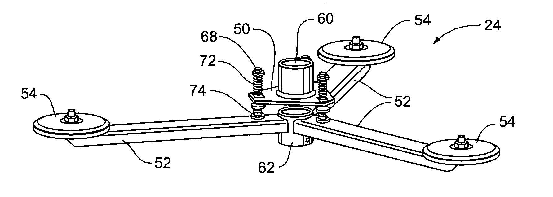
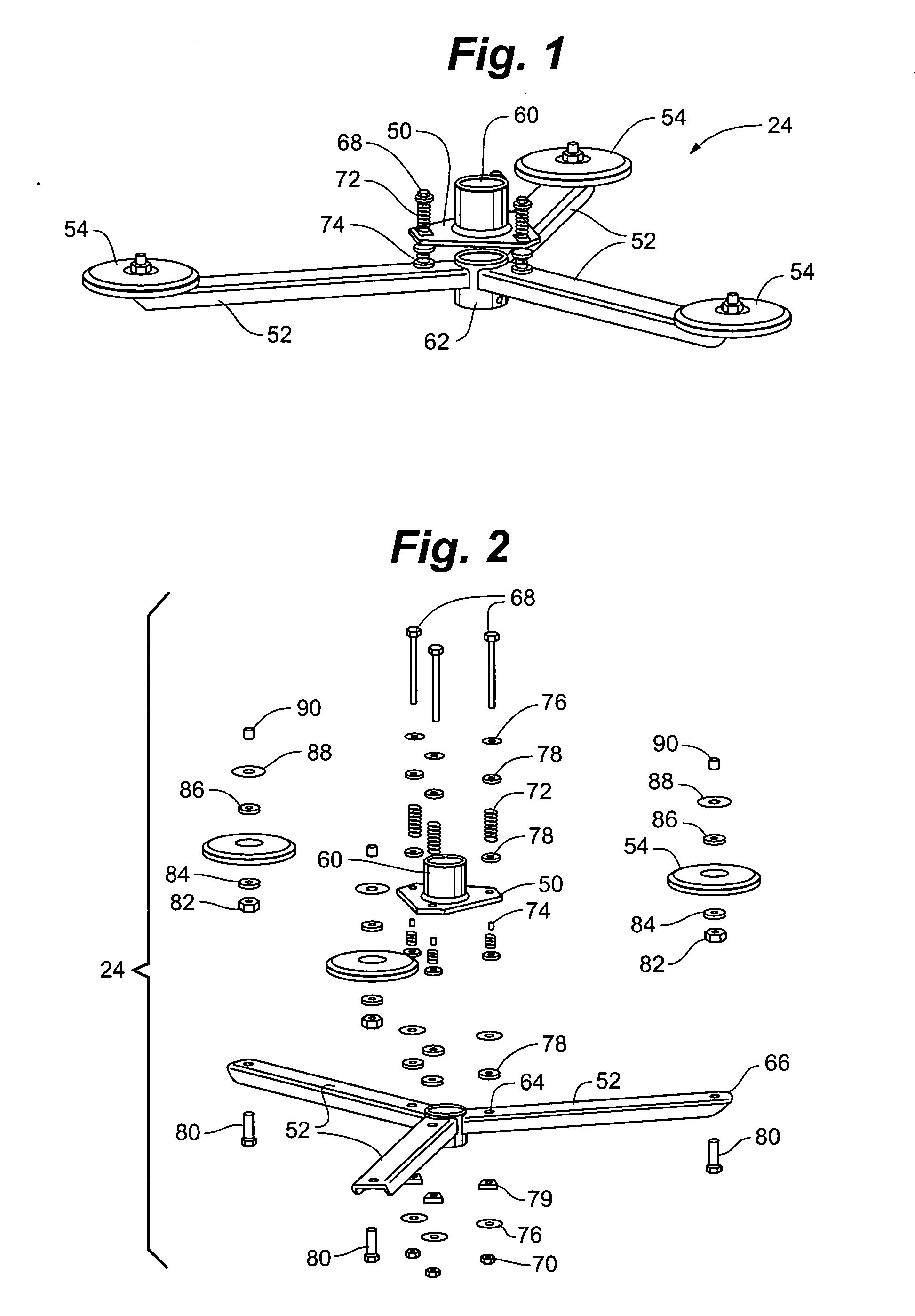
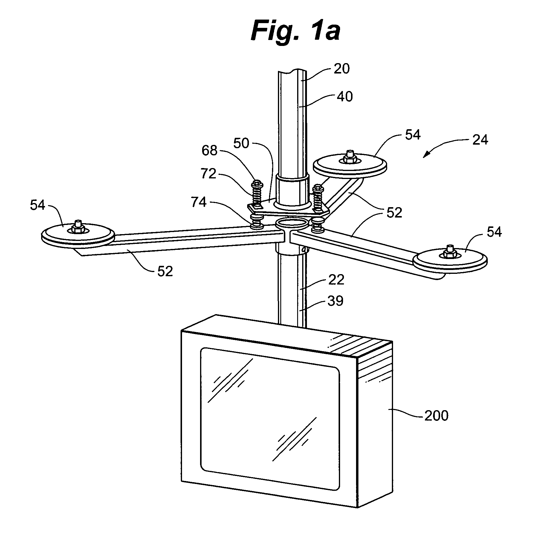
[0026] Referring to FIGS. 1-4c, a vibration dampening mounting system is depicted including an upper mounting portion 20, a lower mounting portion 22 and a vibration dampening portion 24 that is proximate the intersection of the upper mounting portion 20 and the lower mounting portion 22. In some embodiments, upper mounting portion 20 can be adapted to engage with a portion of a ceiling structure, while lower mounting portion 22 can be adapted to engage with a monitor such as, for example, a television, computer monitor, display monitor or the like, a projector, a speaker or combinations thereof.
[0027] In some embodiments, upper mounting portion 20 can include shaft 40 and bracket 42 that is attached to an upper end of shaft 40, while in other embodiments, upper mounting portion includes a pipe coupling and an extension column. Bracket 42 is preferably removably attached to the shaft 40. The length and width of shaft 40 can be selected based upon the weight of the monitor or other ...
PUM
 Abstract
Description
Claims
Application Information