Screen, optical film, and method of manufacturing an optical film

Inactive Publication Date: 2005-10-06
SONY CORP
5 Cites 6 Cited by

AI-Extracted Technical Summary

Problems solved by technology

Therefore, there is a considerable amount of reflection light that does not contribute to viewing, light from the projector cannot be used effectively, and conseq...

Method used

[0115] In this screen 40, the surface of the reflective layer 42 reflects the concave and convex form of the surface of the diffusion layer 43. Since reflection light is scattered according to the shape of the surface thereof, the luminance distribution on the screen 40 is improved.
[0119]...

Benefits of technology

[0055] This manufacturing method facilitates the adjustment of the distribution of diffusion characteristics of the surface of the optical film. Thus, the direction of the scattered light can be controlled according to the position on the surface of the optical film. By using this optical film in a screen, the luminance distribution on the screen is made even while effectively utilizing the projector light. In other words, in the first and second embodiments of the method of the pr...

Abstract

There is provided a screen, which, with a simple configuration, is capable of effectively utilizing light projected thereon and realizing an even luminance distribution on the screen. This screen has a diffusion layer whose diffusion characteristic expressed as a luminance distribution with respect to a scattering angle of incident light incident at an angle of 0° is varied such that the peak position of the luminance distribution is shifted towards a greater value of scattering angle in the direction of the central portion of the screen the greater the distance from the central portion of the screen is. The present invention also provides an optical film suitable for use in such a screen, and a manufacturing method therefor.

Application Domain

MirrorsDiffusing elements +2

Technology Topic

DiffusionDiffusion layer +3

Image

  • Screen, optical film, and method of manufacturing an optical film
  • Screen, optical film, and method of manufacturing an optical film
  • Screen, optical film, and method of manufacturing an optical film

Examples

  • Experimental program(1)

Example

[0076] Hereinafter, a front projector screen related to a first embodiment of the present invention is described with reference to the accompanying drawings. It is to be noted, however, that the configuration described below is merely an example, and the present invention is not limited thereto.
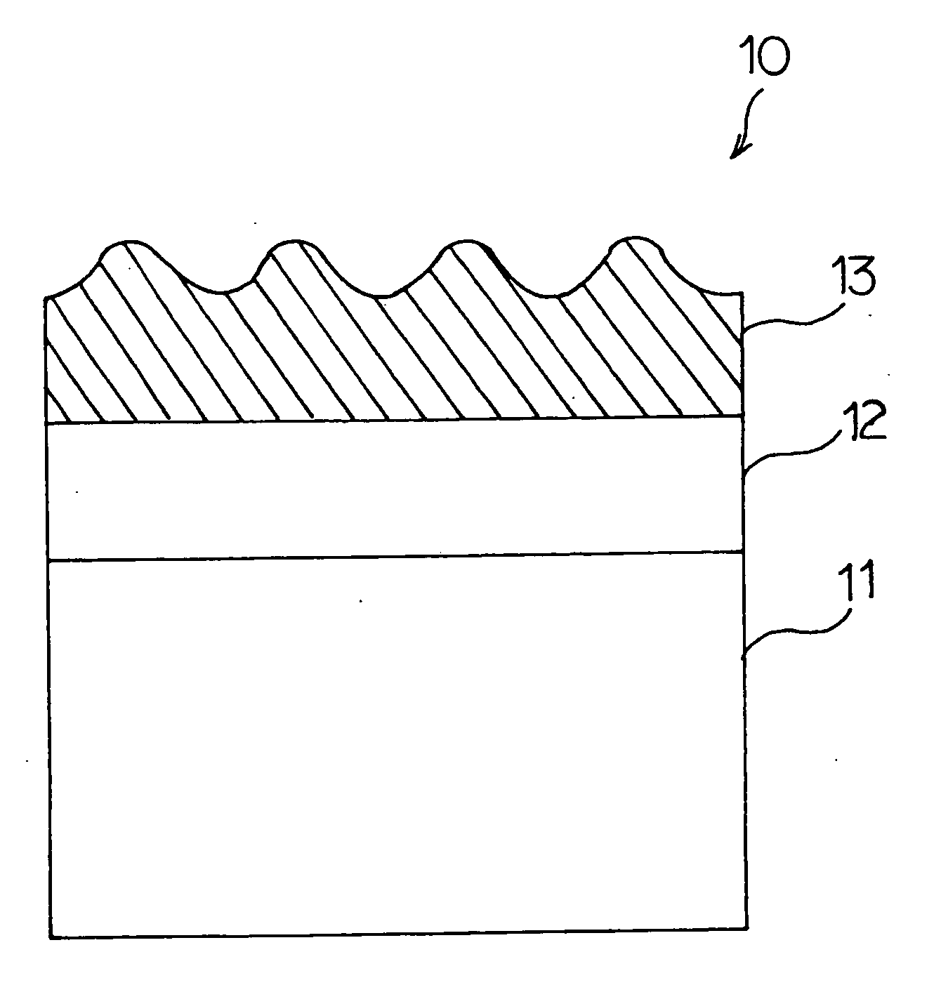
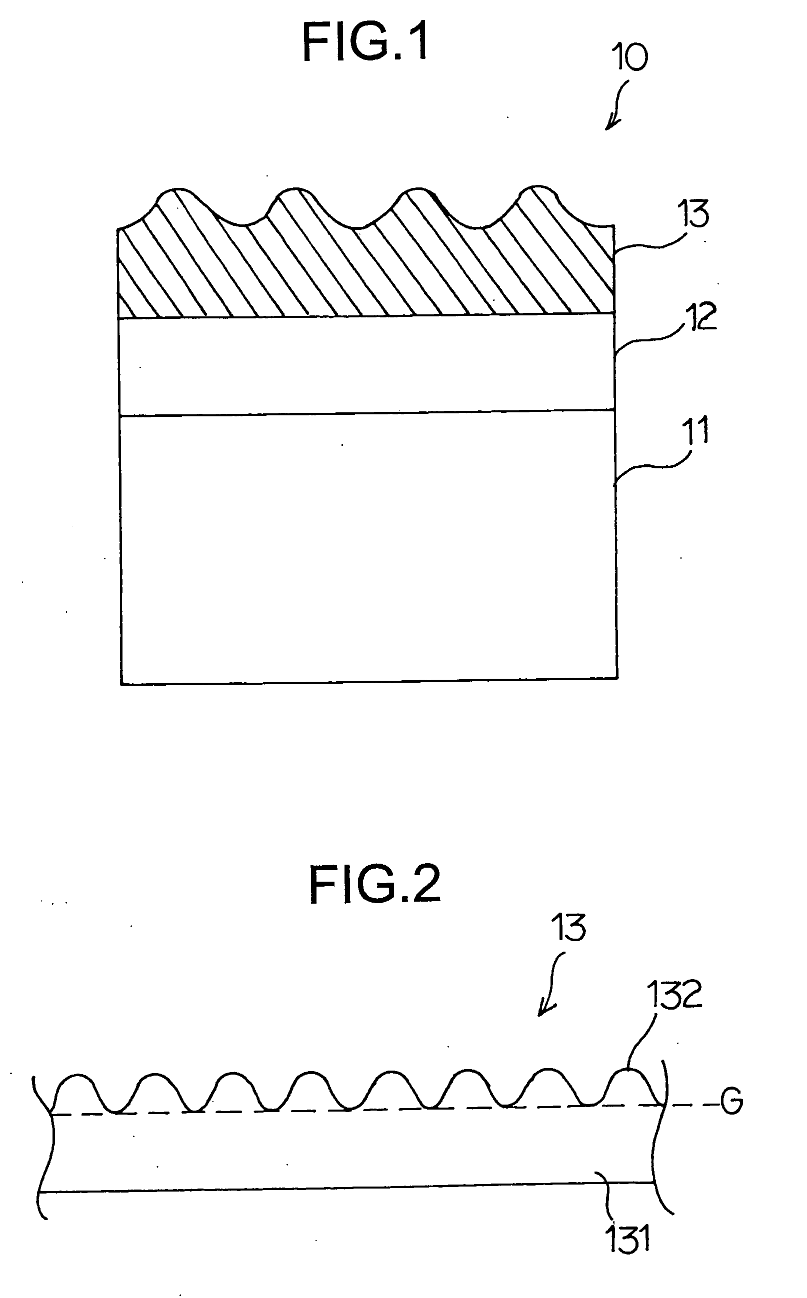
[0077]FIG. 1 is a sectional view showing a configuration related to the first embodiment of the present invention. As shown in FIG. 1, a front projector screen 10 has a reflective layer 12 provided on a screen substrate 11, and a diffusion layer 13 provided thereon.
[0078] The screen substrate 11 is a support member of the front projector screen. Various materials may be used for the screen substrate 11, as long as the material has strength sufficient for use as a screen. For example, such a material may include polymers, such as polyethylene terephthalate (PET), polyethylene naphthalate (PEN), polyether sulfone (PES), and polyolefin (PO).
[0079] The reflective layer 12 has the function of reflecting light projected from a projector. Metal materials with high reflectance, such as aluminum, and materials that reflect light, such as photoluminescent pigments, may be used for the reflective layer 12. This reflective layer 12 can be formed on a surface of the screen substrate 11 by evaporation or by coating. Alternatively, a metal thin film, a metal plate, or a metal evaporated film may be placed on the screen substrate 11. Alternatively, the screen substrate 11 may be formed of a reflective material.
[0080] The diffusion layer 13 scatters the light that is reflected by the reflective layer 12 to obtain scattered light. The diffusion layer 13 may be made of a light-transmissive material, such as resin, for example. A viewer can view a natural image by observing the scattered reflection light.
[0081] Hereinafter, the diffusion layer serving as an optical film is described in more detail.
[0082]FIG. 2 is a sectional view showing the configuration of the diffusion layer 13 provided at the central part of the front projector screen 10.
[0083] The surface on one side of the diffusion layer 13 has concave and convex parts. This, for example, may be seen as a configuration in which the diffusion layer 13 has a plurality of convex parts 132 on a surface G of a flat layer 131. This flat layer 131 and the convex parts 132 are made of the same material, such as an epoxy resin.
[0084] This convex part 132 has a section shaped like a laterally symmetrical chevron having a vertex P, as shown in, for instance, FIG. 3A. The gradient of a slope of the convex portion 132 is the same at any section of the convex part 132. This gradient is taken to be a reference gradient. As shown in FIG. 3B, the shape of the convex part 132 is circular when observed from above. In other words, the virtual cross-section of a bottom surface portion of the convex part 132 along plane G is circular. The normal to the bottom surface from the vertex P passes through a center C of the bottom surface.
[0085] The convex parts 132 each having the above-mentioned shape are formed with a constant pitch at the central portion of the front projector screen 10.
[0086] In an embodiment of the present invention, the shape of each of the convex parts, that is, the gradient of the slope of each of the convex parts, is adjusted according to the position of the convex parts on the front projector screen 10 with the above-mentioned shape of the convex part as a reference, and the luminance distribution on the entire screen is made even by adjusting the diffusion characteristics of the diffusion layer at each position on the screen.
[0087] As an example, the relationship between the position of the convex parts on the front projector screen 10 and the position of the vertex of each of the convex parts is shown in FIG. 4.
[0088] As shown in FIG. 3, the vertex Pb is positioned right above the center of the circular bottom surface of the convex part at a central portion b of the screen 10. As the position of the convex part is shifted towards a peripheral portion of the screen 10, the position of the vertex above the circular bottom surface is shifted from the center of the bottom surface in the direction opposite the direction in which the convex section is shifted.
[0089] For example, if the circular bottom surfaces in FIG. 4 were to be expressed in two-dimensional X-Y coordinates, where the horizontal axis is taken to be the X-axis and the vertical axis is taken to be the Y-axis, the vertex Pa of the convex part placed at point a to the left of the central part b of the screen 10 is shifted to the right side (in the positive direction of the X-axis) of the center C of the circular bottom surface. FIG. 5 illustrates how the position of the vertex of that convex part is shifted. The shape of the cross-section of the convex part is an asymmetric chevron. The gradient of the slope closer to the central part b of the screen 10 (on the right side of the chevron) is greater than that of the slope on the other side. The gradient of this slope is made proportional to the distance from the central part b of the screen 10 (that is, the distance from the central part b to point a). Alternatively, the distance ΔLa, by which the vertex Pa is shifted from the center Ca of the circular bottom surface, may be made proportional to the distance by which the convex section is shifted from the central part b of the screen 10 to point a.
[0090] Regarding the convex part placed at point c to the right of the central part b of the screen 10, the relationship described above is reversed. In other words, as shown in FIG. 6, the cross section of the convex part 132c is a laterally asymmetric chevron. The gradient of the slope on the side of the central part b of the screen 10 (the left side of the chevron) is made greater. The gradient of this slope is made proportional to the distance from the central part b of the screen 10 (that is, the distance between the central part b and point c).
[0091] As described above, all the convex parts positioned away from the central part b of the screen 10 have the gradient of their slope closer to the central part b made larger than the reference gradient, and the gradient is made proportional to the distance by which they are shifted from the central part b of the screen 10.
[0092] For instance, when the convex part is shifted upward from the central part b of the screen 10, the position of the vertex above the circular bottom surface is shifted downward from the center of the bottom surface (that is, downward along the Y-axis (i.e., the negative direction)) thereby adjusting the gradient of the slope. In other words, the distance by which the vertex of the convex parts at points, for example, d and e is shifted from the center of their bottom surfaces is increased in proportion to their distance from the central part b, thereby increasing the gradient of their slopes that are closer to the central part b.
[0093] The direction in which the vertex above the circular bottom surface is shifted is not limited to the directions of the X-axis and the Y-axis. For example, when the convex part is placed at point f positioned to the lower-right of the central part b of the screen 10, the gradient of the slope on the upper left side is made larger.
[0094] The surface of the diffusion layer related to the present invention may include a plurality of convex parts or, alternatively, a plurality of concave parts as long as the gradient of the slopes of the concave or convex parts is adjusted in the manner described above. In addition, the gradient and the curvature of the slopes may be set according to the refraction index of the material of the diffusion layer and the desired luminance distribution on the screen.
[0095] It is necessary that the size of each of the convex parts or the concave parts and their pitch be sufficiently small as compared with the size of a pixel. Preferably, the pitch of the convex or concave parts, that is, the distance between adjacent convex or concave parts should be about 10 μm.
[0096] Because image failures, such as moiré images, sometimes occur due to interference of scattered reflection light when the convex parts or concave parts are arranged regularly on the screen, it is preferable that the convex parts or the concave parts be positioned randomly.
[0097]FIG. 7 shows the diffusion characteristics of reflection light from the diffusion layer 13 in which the position of the vertexes of the convex parts are adjusted in the manner described above. This figure shows diffusion characteristics of convex parts 13a, 13b, and 13c positioned at the left side, the central part, and the right side of the screen 10, respectively.
[0098] The diffusion characteristic of the convex part 13b provided at the central part of the screen 10 shows a curve whose luminance is highest at a scattering angle of 0° as in the diffusion characteristics shown in FIG. 18B. As opposed thereto, the diffusion characteristics of the convex parts 13a and 13c positioned at the left side and the right side of the screen 10, respectively, are such that the peak luminance is shifted towards a greater value of scattering angle in the direction of the central part of the screen 10.
[0099] In other words, a front projector screen related to an embodiment of the present invention may have a characteristic where, when the diffusion characteristics of the screen as a whole are considered, all peripheral parts (upper, lower, left and right) have diffusion characteristics where the peak of the luminance distribution of reflection light is shifted towards greater values of scattering angle in the direction of the central part of the screen 10, and there is a tendency for this shift to become larger in a continuous manner the greater the distance from the center portion of the screen is.
[0100]FIG. 8 shows how light is reflected when the front projector screen 10 having such diffusion characteristics is actually used.
[0101] When light is projected from a light source 70 onto the screen 10, since the luminance distribution of scattered reflection light is biased towards the central part of the screen according to the scattering characteristics, the distribution of scattered reflection light at the peripheral parts of the screen is similar to that at the central part of the screen, whereas in the conventional screen, a large portion of the scattered reflection light at the peripheral parts is directed outward. In other words, with respect to all of the left-side part 10a, the central part 10b, and the right-side part 10c, angular components R10a, R10b, and R10c each having the highest light intensity of the light reflected therefrom are returned to the side of the viewer 80. Thus, the luminance distribution across the entire screen is made even at a high level.
[0102] The foregoing description of the present invention describes an embodiment in which the gradient of the slope of each of the convex parts changes in a continuous manner as the distance between the central part of the screen and each of the convex parts increases. Alternatively, a screen 20 may be divided evenly in the vertical and horizontal directions into areas A1 to A12 and the shapes of convex parts may be made uniform within each of the areas while the gradient of the slope of each of the convex parts are adjusted to vary between the areas. Since the luminance difference between the areas will become apparent if the diffusion characteristics are altered drastically between the areas, and the image will therefore look mosaic-like, it is necessary that the size of the areas be small enough so that the luminance difference will not noticeable.
[0103] The front projector screen 10 described above related to the present invention is manufactured in, for example, the following way.
[0104] As the screen substrate, a screen substrate 11 of a PET film is prepared. A reflective layer 12 comprised of an aluminum layer is formed on one of the surfaces of the screen substrate 11. If an aluminum layer is used as described above, the reflective layer 12 is formed by vacuum evaporation, sputtering, or the like.
[0105] On the other hand, a UV curable epoxy resin liquid is coated to a predetermined thickness on another substrate of PET film. A master mold having predetermined concave and convex shapes formed thereon in advance is placed on the resin liquid layer, and embossing is performed by applying a constant pressure. Thereafter, ultraviolet light is irradiated thereon to thereby harden the UV resin liquid layer. Thus, an optical film to serve as the diffusion layer 13 is formed. The concave and convex shapes to be formed on the master mold is the mirror image of the convex parts, whose gradient of the slope is adjusted according to the position of the convex parts, on the screen 10 described in the embodiment above.
[0106] The diffusion layer 13 formed in this manner is adhered onto the surface of the screen substrate 11 on which the reflective layer 12 is formed to thereby produce the front projector screen 10 related to an embodiment of the present invention.
[0107] Next, another front projector screen related to an embodiment of the present invention is described.
[0108]FIG. 10 is a sectional view showing the configuration of this embodiment of a front projector screen. The configuration of a screen 30 according to the present embodiment is obtained by replacing the reflective layer 12 in FIG. 1 with a selective reflective layer 32. A diffusion layer 33 is formed on the selective reflective layer 32. An absorption layer for absorbing light transmitted through the selective reflective layer 32 is formed on or in the screen substrate 31. This absorption layer is formed by applying a black paint onto a surface of the substrate or by having black microparticles be contained in the substrate.
[0109] The selectively reflective layer 32 is an optical thin film that has properties where light in the wavelength range of projector light, for instance, light in the wavelength ranges of the three primary colors red (R), green (G), and blue (B), is reflected and light that is not within the wavelength ranges of the three primary colors is transmitted. For example, an optical multilayer film proposed in Japanese Patent Application No. 2002-070572 may be used as the selective reflective layer 32. This optical multilayer film includes alternately stacked high-refractive-index layers and low-refractive-index layers and is designed in such a way as to selectively reflect light of a specific wavelength range, such as the wavelength ranges of the three primary colors, as shown in FIG. 11.
[0110] In manufacturing a front projector screen related to this embodiment of the present invention, the step of forming the reflective layer mentioned in the previous manufacturing method is replaced with the step of forming the selective reflective layer by a vacuum thin film forming method, such as evaporation or sputtering, or by a coating method using a solvent. In the case of the vacuum thin film forming method, the selective reflective layer is formed by alternately stacking high-refractive-index layers made of a high-refractive-index material, such as TiO2, Nb2O5, Ta2O5 or the like, and low-refractive-index layers made of a low-refractive-index material, such as SiO2, MgF2 or the like through, for example, AC sputtering. In so doing, the thickness of each of the layers is preliminarily designed according to the wavelength range of the light to be used. Alternatively, in the case of the coating method, thermosetting resins having different refractive indices, for example, are used for the high-refractive-index layers and the low-refractive-index layers.
[0111] This screen 30 enables, when, for example, light from an RGB light source of a diffraction grating projector using a grating light valve (GLV) is projected thereon, viewers to view high-contrast images with less interference from external light and whose luminance distribution on the screen 30 is even. Similar effects can still be obtained when the selectively reflective layer 32 is an optical thin film that reflects light of a specific wavelength range and absorbs light of wavelength ranges other than the specific range mentioned above.
[0112] Next, another front projector screen related to an embodiment of the present invention is described below.
[0113]FIG. 12 is a sectional view showing the configuration in this embodiment of the present invention. The configuration of a screen 40 is such that the arrangement of the reflective layer 12 and the diffusion layer 13 shown in FIG. 1 is switched, that is, a reflective layer 42 is formed on a diffusion layer 43. The materials, the form and the properties of each of a screen substrate 41, the diffusion layer 43, and the reflective layer 42 are the same as those of the corresponding layers described with reference to FIG. 1.
[0114] A method of manufacturing the front projector screen according to this embodiment of the present invention is one in which merely the order in which the step of forming the reflective layer and the step of forming the diffusion layer are performed in the previously described manufacturing method is switched.
[0115] In this screen 40, the surface of the reflective layer 42 reflects the concave and convex form of the surface of the diffusion layer 43. Since reflection light is scattered according to the shape of the surface thereof, the luminance distribution on the screen 40 is improved.
[0116] Next, another front projector screen related to an embodiment of the present invention is described below.
[0117]FIG. 13 is a sectional view showing the configuration in this embodiment of the present invention. The configuration of a screen 50 is such that the arrangement of the selectively reflective layer 32 and the diffusion layer 33 shown in FIG. 10 is switched, that is, a reflective layer 52 is formed on a diffusion layer 53. The materials, the form and the properties of each of a screen substrate 51, the diffusion layer 53, and the selectively reflective layer 52 are the same as those of the corresponding layers described with reference to FIG. 10.
[0118] A method of manufacturing the front projector screen according to this embodiment of the present invention is one in which merely the order in which the step of forming the selectively reflective layer and the step of forming the diffusion layer are performed in the previously described manufacturing method related to FIG. 10 is switched.
[0119] In this screen 50, the surface of the selectively reflective layer 52 reflects the concave and convex form of the surface of the diffusion layer 53. Since reflection light is scattered according to the shape of the surface thereof, the luminance distribution on the screen 50 is improved.
[0120] Next, a rear projector screen related to an embodiment of the present invention is described below with reference to the accompanying drawings.
[0121]FIG. 14 is a sectional view showing the configuration in this embodiment of the present invention. As shown in FIG. 14, a rear projector screen 100 has a configuration in which a diffusion layer 103 is provided on a screen substrate 101.
[0122] The screen substrate 101 functions as a support member of the rear projector screen, and may be comprised of polymers, such as, for example, polyethylene terephthalate (PET), polyethylene naphthalate (PEN), polyether sulfone (PES), and polyolefin (PO) and the like.
[0123] The diffusion layer 103 is comprised of a flat layer 104 and a plurality of convex parts 105 formed on one side of the flat layer 104. The flat layer 104 and the convex parts 105 are made of the same material. The diffusion layer 103 produces scattered light by scattering light that is transmitted through a selectively absorptive layer 101. The diffusion layer 103 is made of a light-transmissive material, such as, for example, an epoxy resin. A viewer is able to view a natural image by observing the scattered light.
[0124] The shape of the surface of this diffusion layer 103 is similar to that of the surface of the diffusion layer in a front projector screen. The surface of the diffusion layer 103 has concave and convex parts due to the convex parts 105. In the present invention, the luminance distribution on the screen as a whole is made even by adjusting the shape of the convex parts 105 according to the position of the convex parts 105 on the rear projector screen 100 to thereby adjust the diffusion characteristics of the diffusion layer according to the position on the screen.
[0125] The same principles as those of the convex sections on the diffusion layer of a front projector screen as mentioned above apply in adjusting the shape of the convex parts 105. In other words, the convex parts provided at the central portion of the screen 100 have an even gradient that is taken to be the reference gradient. All the convex parts placed away from the central portion of the screen 100 are so formed that, of the slopes of each of the convex parts, the slope closer to the central portion has a gradient that is larger than the reference gradient, and that the gradient is made proportional to the distance by which the convex part is shifted from the central portion of the screen 100.
[0126] Thus, the rear projector screen 100 to which the diffusion layer 103, of which the gradient of the slopes of the convex parts are adjusted, is applied has such a characteristic where the diffusion characteristics of all the peripheral parts (upper, lower, left and right) are such that the peak of the luminance distribution of transmitted light is biased in the direction of the central portion of the screen 100. This rear projector screen 100 exhibits a tendency for the bias to become larger in a continuous manner the greater the distance by which the convex part is shifted away from the central portion of the screen is.
[0127]FIG. 17 shows how light is transmitted when the rear projector screen 100 having such diffusion characteristics is actually used.
[0128] When light is projected from a light source 700 onto the screen 100, the luminance distribution of scattered and transmitted light is biased towards the central portion of the screen according to the diffusion characteristics, whereas in the conventional screen, a substantial portion of the transmitted light is directed outward at its peripheral portions. Consequently, the luminance distribution of the scattered and transmitted light at the peripheral portions of the screen is similar to that of the central portion. In other words, with respect to all of the left-side portion 100a, the central portion 100b, and the right-side portion 100c, angular components T100a, T100b, and T100c, each having a light intensity that is the highest of the transmitted light therefrom, are returned to the side of a viewer 800. Thus, the luminance distribution across the entire screen is made even at a high level.
[0129] The foregoing description of the present invention describes an embodiment in which the gradient of the slope of each of the convex parts is gradually changed as the distance between the central portion of the screen and each of the convex parts increases. However, the present invention is not limited as such, and the screen, for example, may be divided evenly in the vertical and horizontal directions into a plurality of areas where the shape of the convex parts within an area is made uniform while the gradient of the slope of the convex parts is varied between the areas.
[0130] As described in the foregoing description related to FIG. 1, the rear projector screen 100 related to the present invention is manufactured by adhering the diffusion layer 103, which is separately formed on a film, onto one of the surfaces of the screen substrate 101 comprised of, for instance, a PET film.
[0131] Next, another rear projector screen related to an embodiment of the present invention is described below.
[0132]FIG. 16 is a sectional view showing the configuration in this embodiment of the present invention. A screen 110 is configured by adding, in addition to the configuration of the embodiment shown in FIG. 14, a selective absorptive layer 112 between a screen substrate 111 and a diffusion layer 113. The screen substrate 111 and the diffusion layer 113 are similar to the corresponding layers found in the embodiment shown in FIG. 14.
[0133] The selective absorptive layer 112 has properties where light of a specific wavelength range, for instance, the wavelength ranges of the three primary colors is transmitted, while light of wavelength ranges not within the specific wavelength range mentioned above is absorbed. For example, as shown in FIG. 15, the selectively absorptive layer 112 transmits light of the wavelength ranges of the three primary colors red (R), green (G), and blue (B), and absorbs light of wavelength ranges not within the ranges of the three primary colors. For example, the optical film proposed in Japanese Patent Application No. 2002-331993 is used as the selective reflective layer 32. This optical film is obtained by dispersing a selectively absorptive dye having absorbing properties for a certain wavelength range(s) outside of a specific wavelength range(s), and transmitting properties for all other wavelength ranges. This optical film can be formed by a coating method using a resin binder.
[0134] The rear projector screen 110 related to the present invention is manufactured by forming the selective absorptive layer 112 on the screen substrate 111 in, for instance, the following way.
[0135] The selective absorptive layer 112 is formed by first preparing a coating material using, with a UV curable resin as a binder, DIARESIN Yellow F (trademark, produced by Mitsubishi Chemical Corporation), which has an absorption peak in the wavelength range of 410 nm to 430 nm, DIARESIN Red S (trademark, also produced by Mitsubishi Chemical Corporation.), which has an absorption peak in the wavelength range of 470 nm to 530 nm, a Squarylium dye, which is described in Japanese Patent Application Publication No. 2002-228829 and has an absorption peak in the wavelength range of 560 nm to 620 nm, and a dye described in Japanese Patent No. 3,308,545, which shows high absorption in the wavelength range equal to or greater than 800 nm. The coating material is applied on one of side of a PET film, which serves as the screen substrate 111, by a spin-coating method. Ultraviolet light is irradiated thereon to thereby cure the UV curable resin.
[0136] Subsequently, the diffusion layer 113, which is separately formed as described above, is adhered onto the selective absorptive layer 112. Thus, the rear projector screen 110 is obtained.
[0137] A front projector screen can be obtained with the above-mentioned configuration by providing a reflective layer between the screen substrate 111 and the selective absorptive layer 112.
[0138] This screen 110 enables viewers to view high-contrast images that have an even luminance distribution on the screen 10, without interference from outside light when light is projected from behind the screen from an RGB light source of a diffraction grating projector using a grating light valve (GLV).
[0139] Since the invention disclosed herein may be embodied in other specific forms without departing from the spirit or general characteristics thereof, some of which forms have been indicated, the embodiments described herein are to be considered in all respects illustrative and not restrictive. The scope of the invention is to be indicated by the appended claims, rather than by the foregoing description, and all changes which come within the meaning and range of equivalents of the claims are intended to be embraced therein.

PUM

no PUM

Description & Claims & Application Information

We can also present the details of the Description, Claims and Application information to help users get a comprehensive understanding of the technical details of the patent, such as background art, summary of invention, brief description of drawings, description of embodiments, and other original content. On the other hand, users can also determine the specific scope of protection of the technology through the list of claims; as well as understand the changes in the life cycle of the technology with the presentation of the patent timeline. Login to view more.

Similar technology patents

Image processing device, image forming device and recording medium

ActiveUS20210349669A1facilitate adjustment
Owner:KONICA MINOLTA INC

Fixing device of shield plate, recording apparatus and liquid ejecting apparatus

ActiveUS20070202745A1reduce variationfacilitate adjustment
Owner:SEIKO EPSON CORP

System to dynamically adjust request values at a back-end application server

ActiveUS10057313B2facilitate adjustment
Owner:HARTFORD FIRE INSURANCE

Rotation Mechanism and Display Supporter

InactiveUS20180368588A1facilitate adjustmentreduce occupied space
Owner:TAIZHOU STRONKIN ELECTRONICS

Jet engine comprising a nacelle equipped with a thrust reversing system comprising doors

InactiveUS20200025139A1facilitate adjustmentsimplifies mechanism
Owner:AIRBUS OPERATIONS SAS

Classification and recommendation of technical efficacy words

  • facilitate adjustment

Intraoral endotracheal tube holder and method for intubation

InactiveUS7063088B1facilitate adjustment
Owner:CHRISTOPHER MARCUS

Sunshade

ActiveUS20050056309A1facilitate adjustment
Owner:CHAVES DANIEL +1

Nose pad assembly for an eyeglass frame

InactiveUS20050052614A1facilitate adjustmentlimit angular range
Owner:NEGISHI TOHRU

Impedance adjusting circuit and impedance adjusting method

InactiveUS20070063731A1facilitate adjustment
Owner:RENESAS ELECTRONICS CORP
Why Eureka
Try Eureka