Angle adjusting mechanism for chair

Inactive Publication Date: 2005-04-14
LIU JIEN FENG
View PDF6 Cites 4 Cited by
  • Summary
  • Abstract
  • Description
  • Claims
  • Application Information

AI Technical Summary

Benefits of technology

[0006] Another objective of the present invention is to provide an angle adjusting mechanism for a chair, wherein the inclined angle of the seat support frame can be easily adjusted by pushing the adjusting bar, thereby facilitating the user adjusting the inclined angle of the chair.
[0007] A further objective of the present invention is to provide an an

Problems solved by technology

However, the conventional angle adjusting mechanism has a comp

Method used


Image

  • Angle adjusting mechanism for chair
  • Angle adjusting mechanism for chair
  • Angle adjusting mechanism for chair

Examples


Embodiment Construction

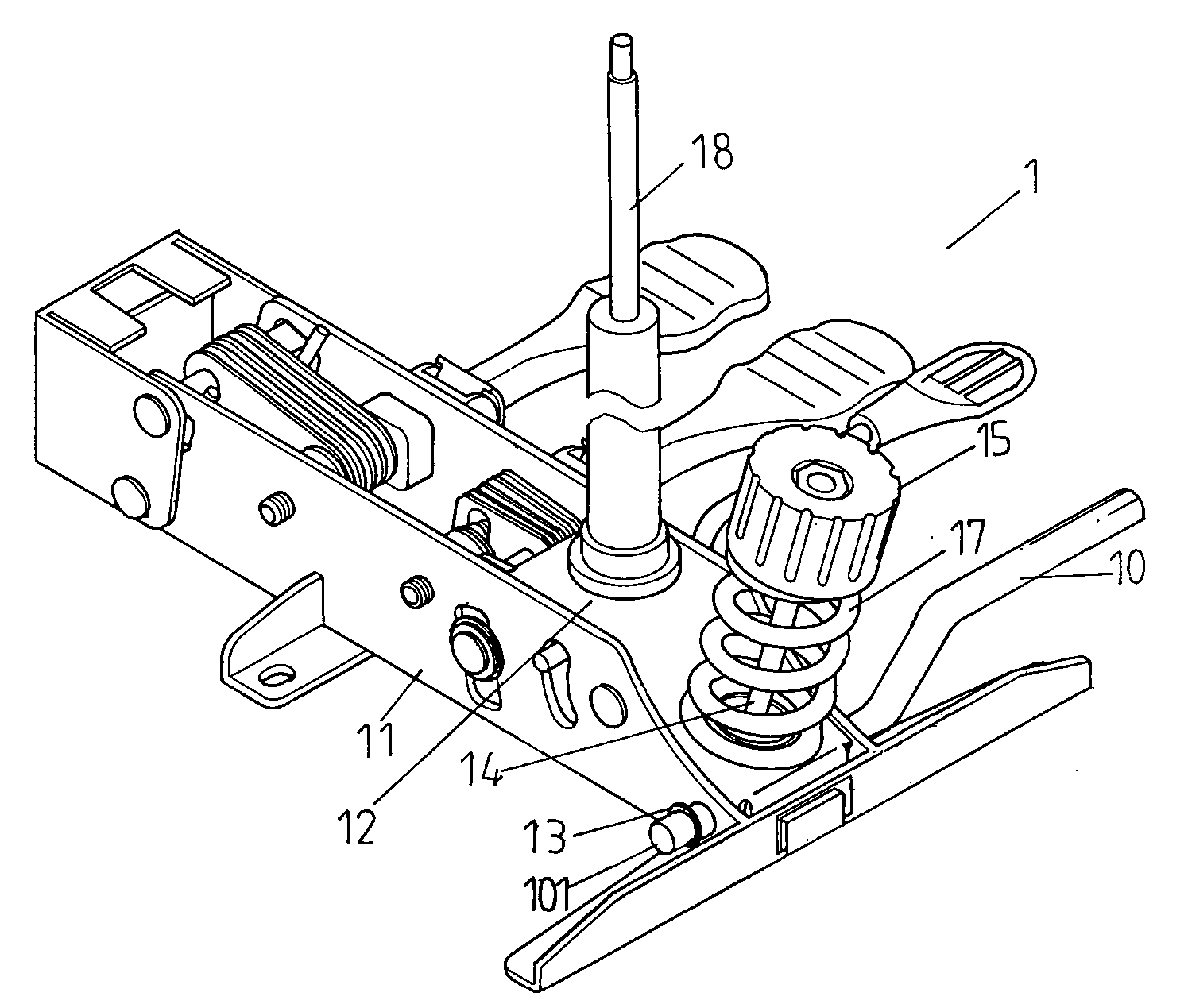
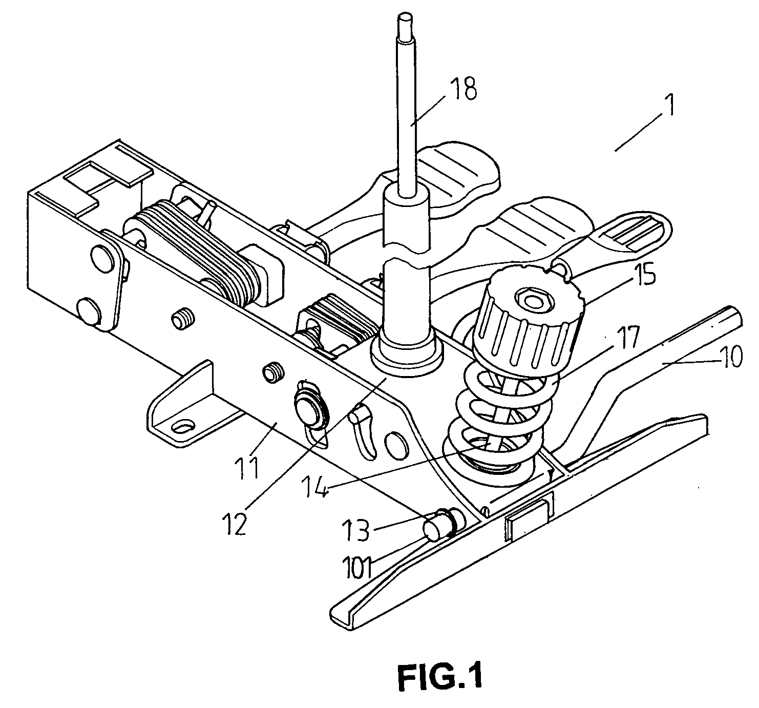
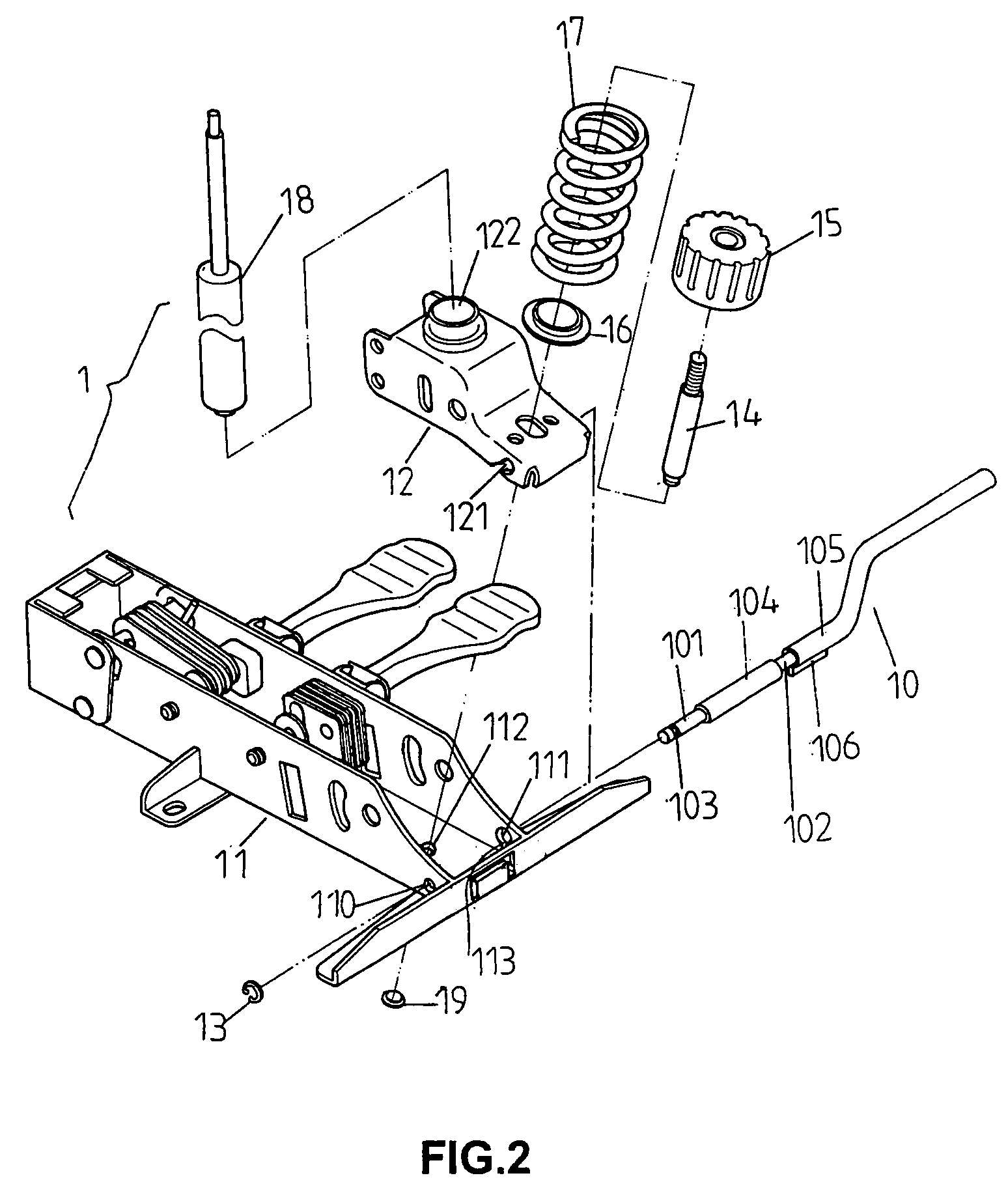
[0026] Referring to the drawings and initially to FIGS. 1-3, an angle adjusting mechanism 1 for a chair in accordance with the preferred embodiment of the present invention comprises a support base 12, a seat support frame 11 pivotally mounted on the support base 12, and an adjusting bar 10 mounted between the support base 12 and the seat support frame 11 for adjusting an included angle between the support base 12 and the seat support frame 11.

[0027] The support base 12 is a hollow body and has two side walls each formed with an adjusting recess 121. The support base 12 has a bottom formed with a receiving recess 122 for receiving a pneumatic bar 18.

[0028] The seat support frame 11 is a hollow body and has a first side wall formed with a first positioning hole 110 and a second side wall formed with a second positioning hole 111. The second positioning hole 111 of the seat support frame 11 aligns with the first positioning hole 110 and has a periphery formed with a guide slot 113. ...


PUM


Abstract

A angle adjusting mechanism for a chair includes a support base, a seat support frame pivotally mounted on the support base, and an adjusting bar mounted between the support base and the seat support frame for adjusting an included angle between the support base and the seat support frame. Thus, the inclined angle of the seat support frame can be easily adjusted by pushing the adjusting bar, thereby facilitating the user adjusting the inclined angle of the chair.

Description

BACKGROUND OF THE INVENTION [0001] 1. Field of the Invention [0002] The present invention relates to an angle adjusting mechanism, and more particularly to an angle adjusting mechanism for a chair. [0003] 2. Description of the Related Art [0004] A conventional angle adjusting mechanism for a chair in accordance with the prior art shown in FIGS. 7 and 8 comprises a support base 23, a seat support frame 20 pivotally mounted on the support base 23, and a drive bar 22 fixed on the seat support frame 20 by a fixing base 21 and a bushing 24 for adjusting an included angle between the support base 23 and the seat support frame 20. The chair includes a seat (not shown) mounted on the seat support frame 20 to move therewith, so that the seat can be disposed at an inclined state by operating the drive bar 22 to change the inclined angle of the seat support frame 20 relative to the support base 23. However, the conventional angle adjusting mechanism has a complicated construction, thereby incr...

Claims


Application Information

Patent Timeline
IPC IPC(8): A47C1/027A47C1/032A47C7/60
CPCA47C1/0325A47C1/027
Inventor LIU, JIEN-FENG
Owner LIU JIEN FENG
Why Eureka
Try Eureka