Lighting device and display device

Active Publication Date: 2018-08-23
SHARP KK
View PDF4 Cites 2 Cited by
  • Summary
  • Abstract
  • Description
  • Claims
  • Application Information

AI Technical Summary

Benefits of technology

[0019]The present invention makes it possible to reduce luminance unevenness

Problems solved by technology

However, when the light sources are arranged in a linear form, it is necessary to linearize a section of an annular wall portion covering the li

Method used


Image

  • Lighting device and display device
  • Lighting device and display device
  • Lighting device and display device

Examples


Example

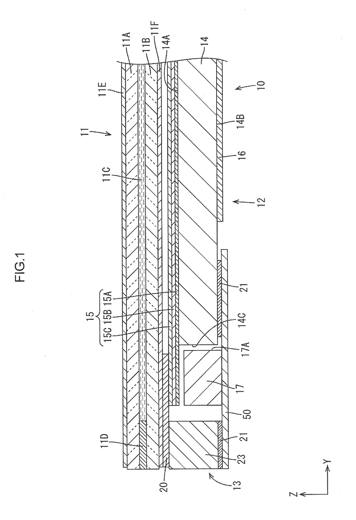
[0043]A first embodiment of the present invention will be described with reference to FIGS. 1 to 7. In the present embodiment, a liquid crystal display device 10 (display device) including a liquid crystal panel 11 is illustrated. The vertical direction of the liquid crystal panel 11 is based on FIG. 1. An upper side and a lower side in FIG. 1 correspond to a front side and a back side of the liquid crystal display device 10, respectively. X-axes, Y-axes, and Z-axes are shown in some drawings. The axes in each drawing correspond to the respective axes in other drawings.

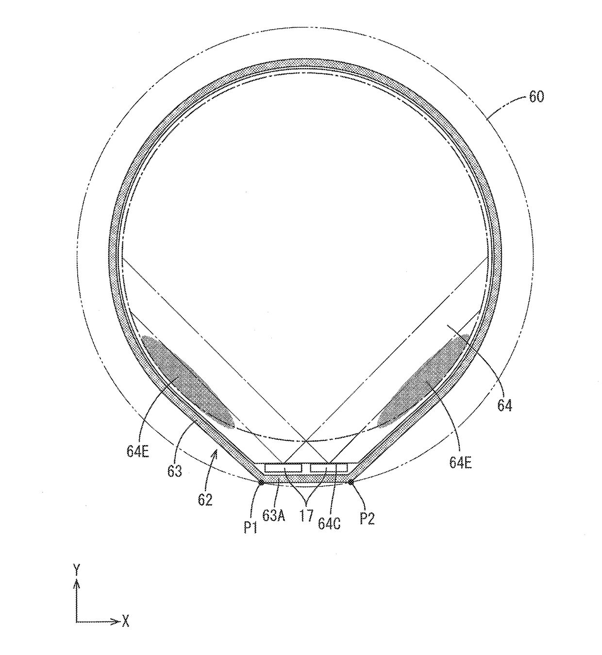
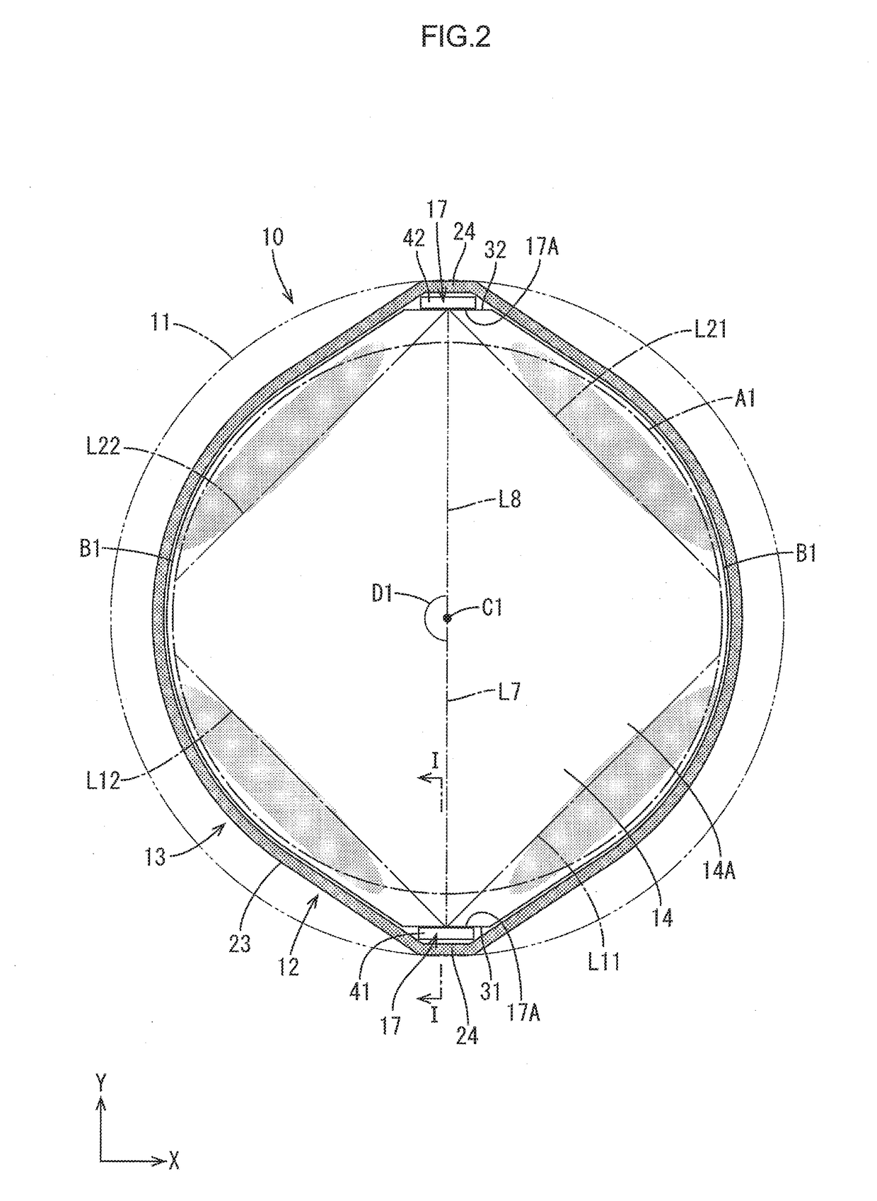
[0044]As shown in FIGS. 1 and 2, the liquid crystal display device 10 has a substantially circular shape as a whole. The liquid crystal display device 10 includes at least a liquid crystal panel 11 configured to display an image, and a backlight device 12 (lighting device) disposed on a back side with respect to the liquid crystal panel 11, and configured to supply light necessary for display to the liquid crystal pan...

Example

Second Embodiment

[0074]Next, a second embodiment of the present invention will be described with reference to FIGS. 8, 9. In a backlight device 112 of the present embodiment, the configuration of a light guide plate is different from that of the above embodiment. The same portions as those of the above embodiment are denoted by the same reference numerals, and redundant description is not repeated.

[0075]In the present embodiment, as shown in FIG. 8, a through hole 114A having a circular shape is formed at the center C1 (the center of the backlight device 112) of a light exiting surface 14A in a light guide plate 114. The through hole 114A is formed so as to penetrate the light guide plate 114 in the thickness direction. Into the through hole 114A, a functional component constituting a liquid crystal display device 10 is inserted. Examples of such a functional component include, but are not limited to, a component involving the driving of a needle of a clock or meter provided on the ...

Example

Third Embodiment

[0078]Next, a third embodiment of the present invention will be described with reference to FIG. 10. In a backlight device 212 of the present embodiment, the configuration of LEDs is different from that of the second embodiment. The same portions as those of the above embodiment are denoted by the same reference numerals, and redundant description is not repeated.

[0079]In the present embodiment, as shown in FIG. 10, optical axes L1, L2 of LEDs 41, 42 are disposed so as not to be overlapped with a light blocking member 115. When light emitted by the LED is reflected by the light blocking member 115, the circumference of the light blocking member 115 is bright, which may disadvantageously cause luminance unevenness. In the present embodiment, the optical axes L1, L2 of the LEDs 41, 42 are disposed so as not to be overlapped with the light blocking member 115, whereby the amount of light directly directed to the light blocking member 115 can be reduced, thereby allowing...


PUM


Abstract

A lighting device includes a light guide plate, a first light source, a second light source, and a case. The light guide plate includes plate surfaces and an outer peripheral surface. One of the plate surfaces is configured as a light exiting surface. Sections of the outer peripheral surface on opposite sides from each other relative to the center of the light exiting surface are configured as a first light entering surface and a second light entering surface, respectively. The first light source is disposed opposite the first light entering surface. The second light source is disposed opposite the second light entering surface. The case includes an annular wall portion surrounding an outer circumference of the light guide plate, the first light source, and the second light source. The annular wall portion includes light source non-disposing areas between the first light entering surface and the second light entering surface.

Description

TECHNICAL FIELD[0001]The present invention relates to a lighting device and a display device.BACKGROUND ART[0002]Conventionally, a display device described in the following Patent Document 1 has been known. Patent Document 1 describes a liquid crystal display device having a display area having a substantially circular shape. As such a display device, there has been known a display device including a lighting device having a substantially circular shape corresponding to the shape of the display device. Such a lighting device includes a light source and a light guide plate having a substantially circular shape. Light from the light source enters the light guide plate and then exits the light guide plate through the light exiting surface.[0003]Patent Document 1: Japanese Unexamined Patent Publication No. 2006-276359Problem to be Solved by the Invention[0004]When a section of the outer peripheral surface of the light guide plate having a substantially circular shape is a light entering...

Claims


Application Information

Patent Timeline
IPC IPC(8): F21V8/00
CPCG02B6/0068G02B6/0045G02B6/0091G02B6/0083
Inventor YUKI, RYUZOKIKUCHI, KATSUTOSHINAKAMURA, HAYATOYOSHIMURA, MAKOTOENOMOTO, HIROMIMURATA, MITSUHIROWATANABE, HISASHIYASUNAGA, HIROTOSHI
Owner SHARP KK
Why Eureka
Try Eureka