High-frequency switch

Inactive Publication Date: 2014-09-11
ORMON CORPORATION
View PDF4 Cites 5 Cited by
  • Summary
  • Abstract
  • Description
  • Claims
  • Application Information

AI Technical Summary

Benefits of technology

[0028]According to this configuration, it is possible to enhance a function or performance of the high-frequency switch. For example, the first and second switches can be controlled (e.g., voltages can be supplied to the first and second switches) by the active element. This may eliminate the need for preparing additional configuration

Problems solved by technology

However, neither U.S. Pat. No. 6,809,255 nor Unexamined Japanese Patent Publication No. 2000-113792 specifica

Method used


Image

  • High-frequency switch
  • High-frequency switch
  • High-frequency switch

Examples


Example

Embodiment 1

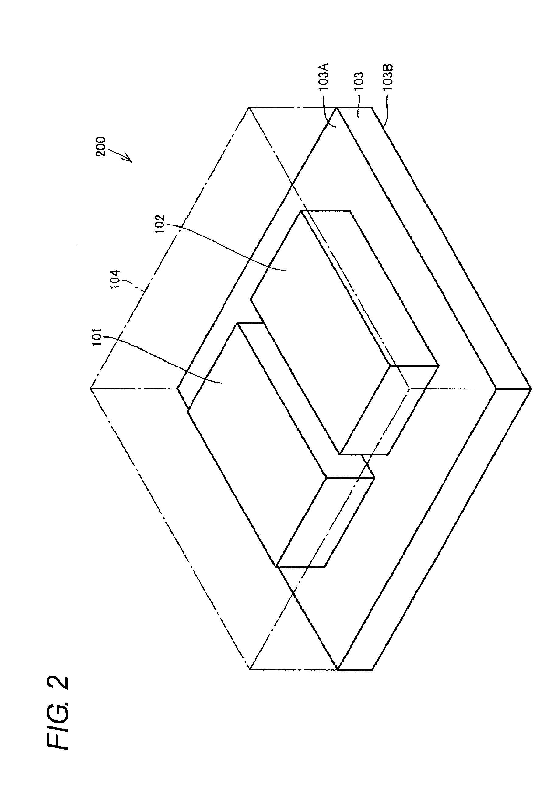
[0133]FIG. 20 is an internal perspective view of a high-frequency switch according to Embodiment 1. Referring to FIG. 20, a high-frequency switch 211 according to Embodiment 1 is provided with the SPDT switches 101, 102, the substrate 103, and the sealing member 104. The high-frequency switch 211 further includes an ASIC (Application Specific Integrated Circuit) 105. The ASIC 105 is arranged on the SPDT switch 102, and sealed by the sealing member 104 along with the SPDT switches 101, 102. The ASIC 105 is connected to the electrodes of the substrate 103 by bonding wires. Further, the electrodes of the SPDT switches 101, 102 are connected to the electrodes of the substrate 103 by soldering, not shown. It is to be noted that the SPDT switches 101, 102 are fixed to the principal surface 103A of the substrate 103 by under filling (not shown), for example. The high-frequency switch 211 may include a passive element such as a capacitor in addition to or in place of an active e...

Example

Embodiment 2

[0143]FIG. 24 is an internal perspective view of a high-frequency switch according to Embodiment 2. Referring to FIG. 24, a high-frequency switch 212 according to Embodiment 2 is different from the high-frequency switch 211 according to Embodiment 1 in including a substrate 106 in place of the substrate 103. The high-frequency switch 212 is different from the high-frequency switch 211 in including a sealing member 107 in place of the sealing member 104. In Embodiment 2, a buildup substrate is adopted as the substrate 106. Further, a cap is adopted as the sealing member 107.

[0144]FIG. 25 is a plan transparent view for explaining a signal line formed on the substrate 106 shown in FIG. 24. Referring to FIG. 25, the input signal line 150a has wiring portions 162a, 163a formed in different wiring layers. The wiring portions 162a, 163a are connected by a via 166a. In the same manner, the input signal line 150b has wiring portions 162b, 163b formed in the different wiring layer...


PUM


Abstract

A high-frequency switch configured to transmit differential signals including first and second signals, has first and second switches each comprising an input terminal configured to receive a signal and two output terminals configured to output the signal, and a substrate comprising a first surface mounted with the first and second switches. The input terminal is arranged between the two output terminals. The first and second switches are arranged on the substrate along a direction intersecting with a direction in which the input terminal and the two output terminals are placed side by side. One terminal of the first switch and one terminal of the second switch are placed side by side along the direction in which the first and second switches are arranged.

Description

CROSS REFERENCE TO RELATED APPLICATIONS[0001]This application claims priority to Japanese Patent Application No. 2013-046709 filed on Mar. 8, 2013, the entire contents of which are incorporated by reference hereinBACKGROUND[0002]1. Technical Field[0003]The present invention relates to a high-frequency switch, and especially relates a high frequency switch suitable for differential transmission.[0004]2. Related Art[0005]A high-frequency switch is used, for example, for switching a channel of high-frequency signals, or switching transmission and cutoff of signals. For example, U.S. Pat. No. 6,809,255 (Patent Document 1) discloses a high-frequency relay having a ground shield. For example, Japanese Unexamined Patent Publication No. 2000-113792 (Patent Document 2) discloses an electrostatic micro relay. In this electrostatic micro relay, fixed electrodes are provided on both sides of a signal line at an equal distance. Further, the fixed electrodes are simultaneously used with a high-fr...

Claims


Application Information

Patent Timeline
IPC IPC(8): H01P1/10
CPCH04L25/0272H01H59/0009H01P1/127
Inventor HORIMOTO, YASUHIROMASUDA, TAKAHIROMORIHARA, DAISUKE
Owner ORMON CORPORATION
Why Eureka
Try Eureka