Rotation Mechanism and Display Supporter

Inactive Publication Date: 2018-12-27
TAIZHOU STRONKIN ELECTRONICS
View PDF1 Cites 2 Cited by
  • Summary
  • Abstract
  • Description
  • Claims
  • Application Information

AI Technical Summary

Benefits of technology

[0024]The rotation mechanism provided in embodiments of the present application is configured to be used for a display supporter. The rotation mechanism includes the holder, the horizontal rotation part and the vertical rotation part. One end of the vertical rotation part is rotationally connected with the holder via the rotation shaft, such that the vertical rotation part rotates about the rotation shaft in the vertical direction. One end of the horizontal rotation part is rotationally connected with the other end of the vertical rotation part via the connection shaft, su

Problems solved by technology

In an existing rotation mechanism of the display supporter, both of a horizontal rotation mechanism and a vertical rotation mechanism are provided

Method used


Image

  • Rotation Mechanism and Display Supporter
  • Rotation Mechanism and Display Supporter
  • Rotation Mechanism and Display Supporter

Examples


Example

First Embodiment

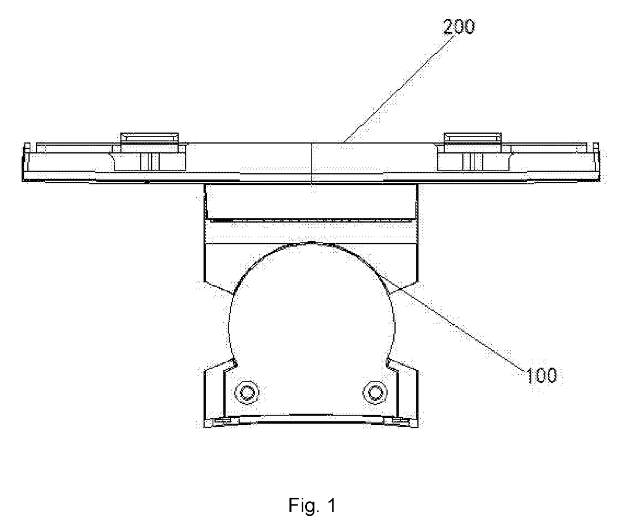
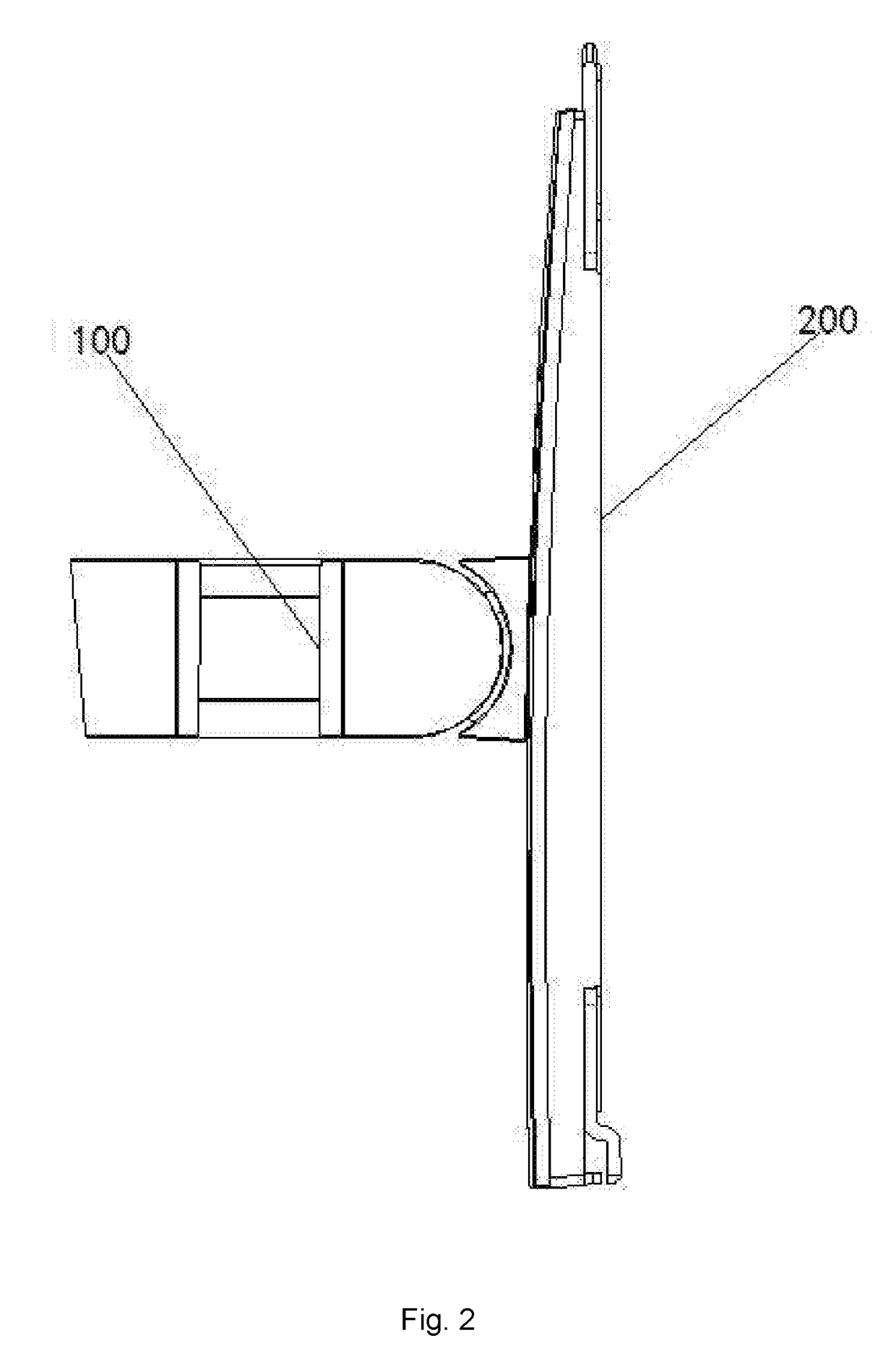
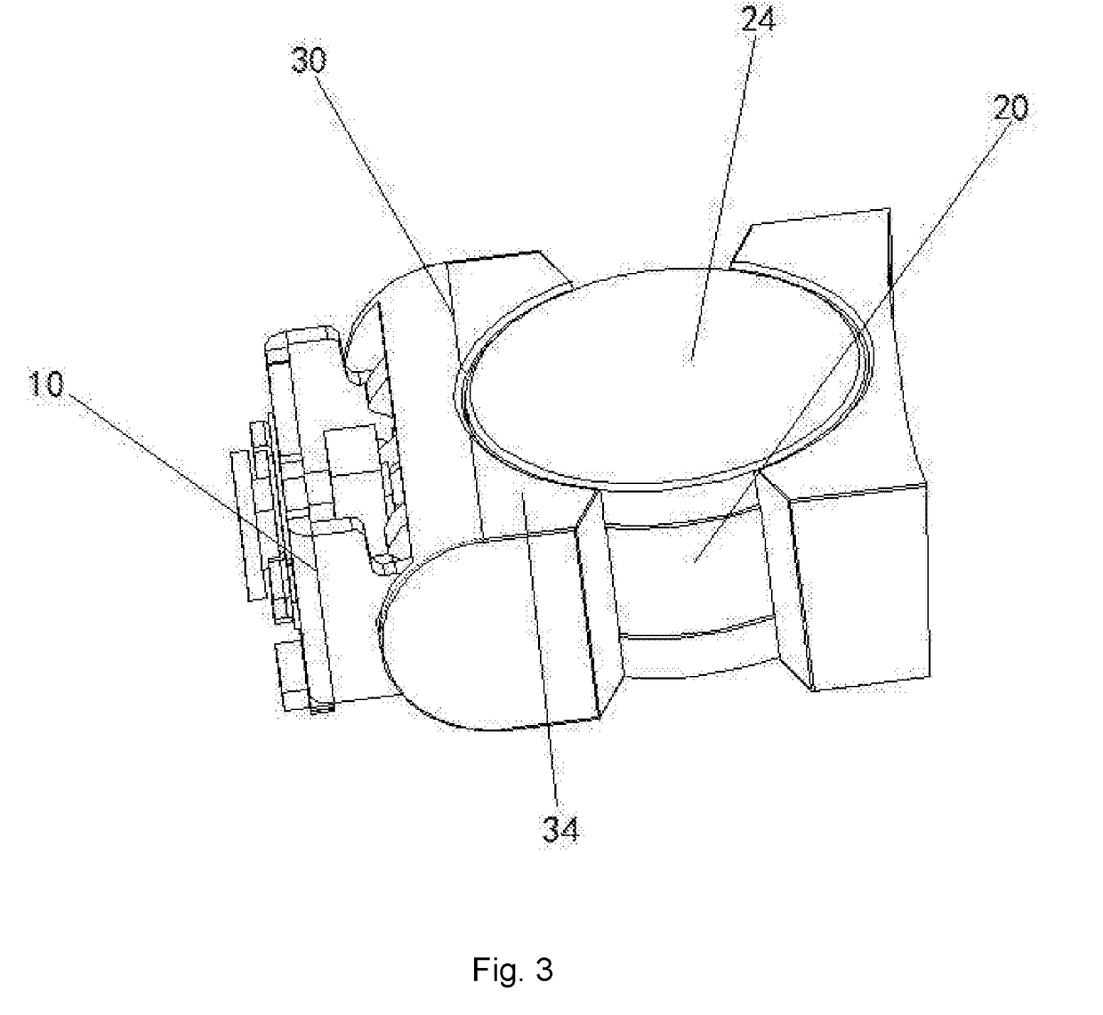
[0041]As shown in FIGS. 1-7, a rotation mechanism 100 provided in the present embodiment is configured to be used for a display supporter 200; and the rotation mechanism includes a holder 10, a horizontal rotation part 20 and a vertical rotation part 30.

[0042]One end of the vertical rotation part 30 is rotationally connected with the holder 10 via a rotation shaft 40, such that the vertical rotation part 30 rotates about the rotation shaft 40 in a vertical direction. One end of the horizontal rotation part 20 is rotationally connected with the other end of the vertical rotation part 30 via a connection shaft 50, such that the horizontal rotation part 20 can rotate about the connection shaft 50 in a horizontal direction.

[0043]The rotation mechanism 100 provided in an embodiment of the present application is configured to be used for the display supporter 200. The rotation mechanism includes the holder 10, the horizontal rotation part 20 and the vertical rotation part ...

Example

Second Embodiment

[0056]As shown in FIG. 1 and FIG. 2, a display supporter 200 provided in the second embodiment of the present application includes the rotation mechanism 100 described in any of the implementations of the abovementioned first embodiment. The holder 10 may be arranged on a base of the display supporter 200 via a bolt.

[0057]The display supporter 200 provided in the second embodiment of the present application is configured with the rotation mechanism 100 provided in the first embodiment. Thus, the displayer holder has all the beneficial effects of the rotation mechanism provided in the first embodiment, which are not repeatedly described herein.

[0058]In conclusion, the rotation mechanism provided in the embodiments of the present application is configured to be used for the display supporter. The rotation mechanism includes the holder, the horizontal rotation part and the vertical rotation part. One end of the vertical rotation part is rotationally connected with the ...


PUM


Abstract

Provided are a rotation mechanism and a display supporter. The mechanism includes a holder, a horizontal rotation part and a vertical rotation part. One end of the vertical rotation part is rotationally connected with the holder via a rotation shaft, such that the vertical rotation part rotates about the rotation shaft in a vertical direction. One end of the horizontal rotation part is rotationally connected with the other end of the vertical rotation part via a connection shaft, such that the horizontal rotation part can rotate about the connection shaft in a horizontal direction. During use, a vertical rotation can be achieved by rotating the vertical rotation part around the rotation shaft, and a horizontal rotation can be achieved by horizontally adjusting the horizontal rotation part with a force. The vertical and horizontal rotation parts are integrated together, which facilitates the adjustment and reduces the occupied space.

Description

CROSS-REFERENCE TO RELATED APPLICATION[0001]The present application claims the priority to Chinese patent application No. 201720736333.X, titled “Rotation Mechanism and Display Supporter”, and filed with the State Intellectual Property Office of the People's Republic of China on Jun. 22, 2016, the content of which is hereby incorporated by reference in its entirety.TECHNICAL FIELD[0002]The present application relates to the technical field of supporting parts of displays and rotation mechanisms, and particularly to a rotation mechanism and a display supporter.BACKGROUND ART[0003]At present, an electronic computer has become one of the necessary devices in our daily life and work. With a progress of science and technology and a rapid advancement of various computer technologies and network technologies, the development of computer has entered a fast and new era, and plays a more and more important role.[0004]In an existing rotation mechanism of the display supporter, both of a horizo...

Claims


Application Information

Patent Timeline
IPC IPC(8): A47F5/00F16M13/02
CPCA47F5/0087F16M13/02F16M2200/021F16M2200/042F16M2200/06F16M11/10F16M11/2014F16M2200/041
Inventor XIA, YONGCHEN, BO
Owner TAIZHOU STRONKIN ELECTRONICS
Why Eureka
Try Eureka