Construction method for upright lifting of large-tonnage box girder to bridge, and erection method for large-tonnage box girder
Active Publication Date: 2022-07-14
CHINA RAILWAY NO 2 ENG GRP CO LTD +1
View PDF4 Cites 0 Cited by
Summary
Abstract
Description
Claims
Application Information
AI Technical Summary
This helps you quickly interpret patents by identifying the three key elements:
Problems solved by technology
Method used
Benefits of technology
Benefits of technology
The present invention is related to a new method for lifting a box girder to a bridge. The lifting station is located below the bridge line and the lifter traveling rail is adjacent to the bridge line and the pier. Compared to side lifting, the new method allows for upright lifting of the cycle which saves land use area, reduces the distance between the lifter and the bridge line, and increases the stability of the apparatus. This makes the apparatus safer and more efficient in use and improves the overall operation efficiency.
Problems solved by technology
The method for filling the temporary road to the bridge has the following defects that: the temporary road must be led out from the middle line of the bridge, which affects the construction of adjacent sections; the bridge floor is large in height difference from the ground, the temporary road is set to be fairly long as limited by climbing capacity of the girder conveying apparatus, and it has a large temporary engineering quantity and a high cost; a special apparatus is required to be arranged in the prefabrication field for taking the girder; it is very difficult to build the road on the soft soil foundation in the mud flat area, and the recovery cost is very high after the project is finished.
The lifting of the apparatus at a side position by the lifting station and the girder to the bridge has the following defects that the required girder lifting apparatus has a large span, a huge land use area and high use risks.
Method used
Image
Click on the blue label to locate the original text in one second.
Reading with bidirectional positioning of images and text.
Examples
embodiment 1
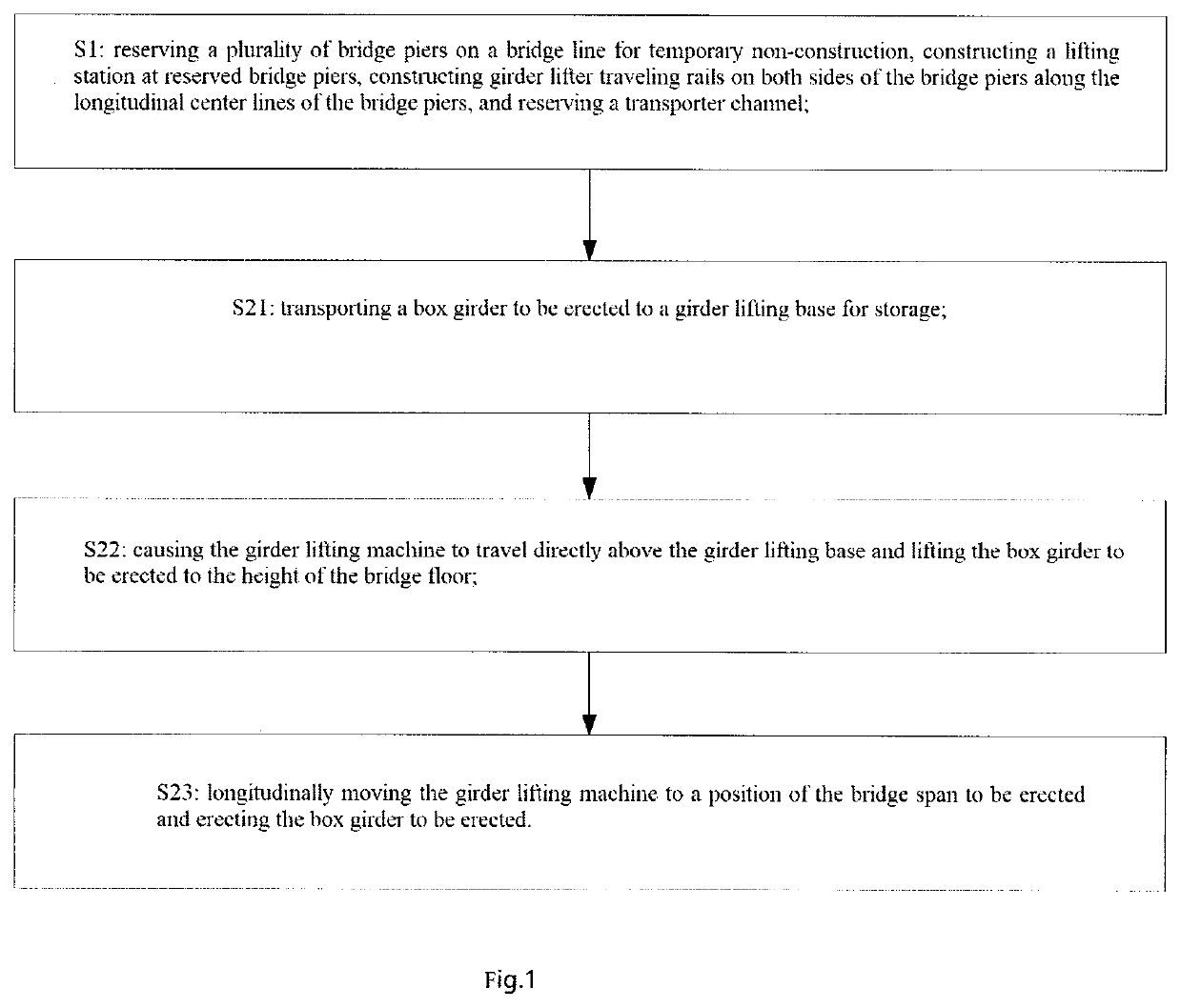
[0083]As shown in FIG. 1, a construction method for the upright lifting of a large-tonnage box girder to a bridge comprises the following steps:
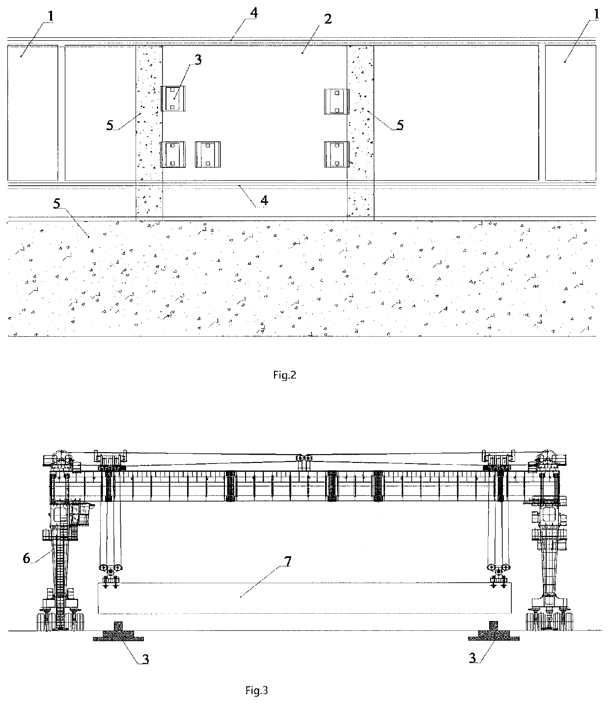
[0084]S1: constructing a lifting station 2;
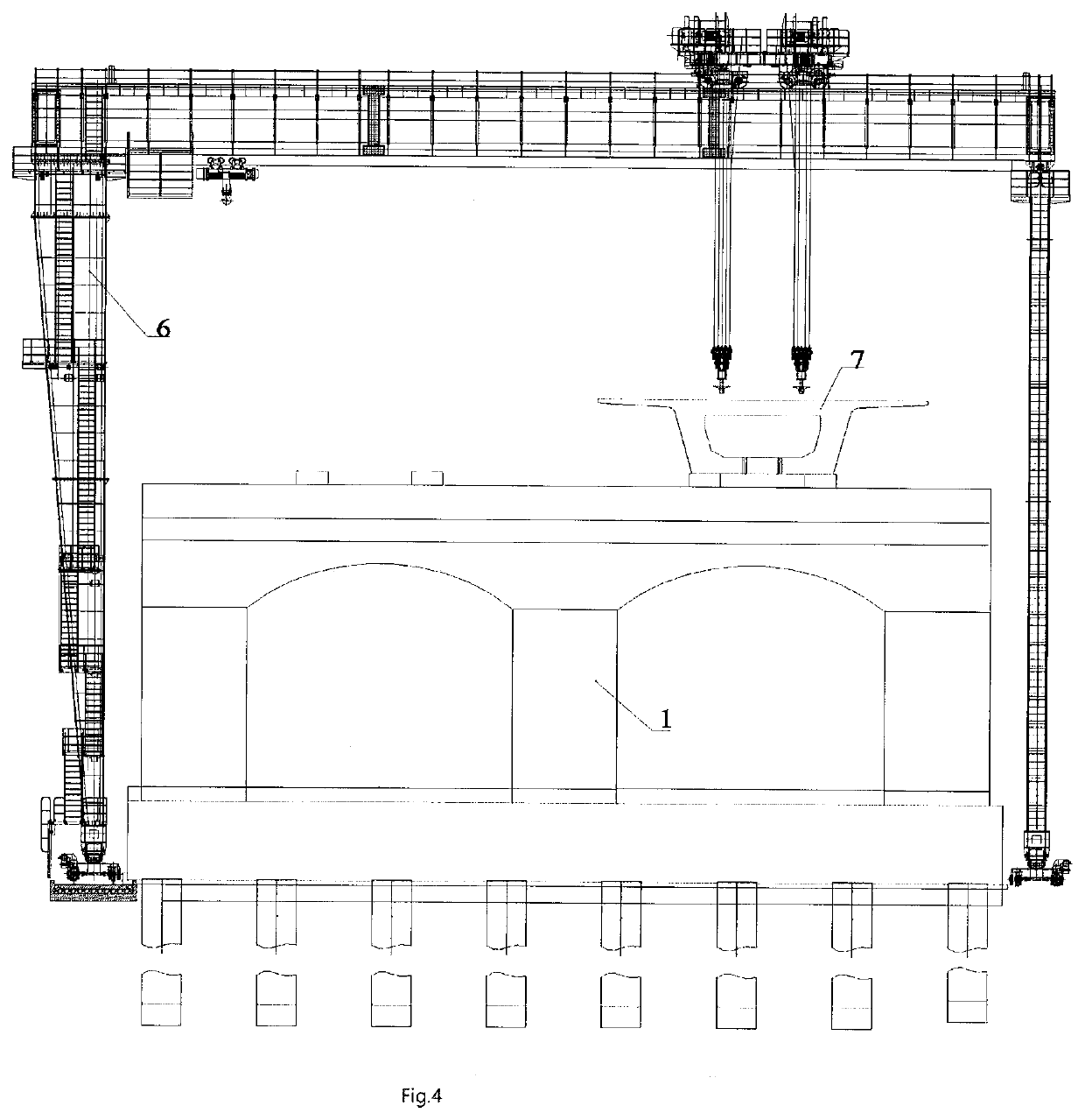
[0085]As shown in FIG. 2, a plurality of bridge piers 1 are reserved on a bridge line for temporary non-construction, a lifting station 2 is constructed at the reserved bridge piers 1, and the center line of the span of the lifting station 2 coincides with the center line of M-shaped bridge piers 1. A plurality of girder lifting bases 3 are arranged in the lifting station 2, and the girder lifting bases 3 are arranged in the middle of the lifting station 2 and are positioned right below the bridge line. An lifter traveling rail 4 is constructed on both sides of the bridge pier 1 along the longitudinal center line of the bridge pier 1, the coverage range of the lifter traveling rail 4 at least comprises three front and rear bridges of the lifting station 2, and an lifter is installed on the lifter tr...
embodiment 2
[0090]As shown in FIG. 6, the embodiment discloses a construction method for the upright lifting of a large-tonnage box girder to a bridge, the construction steps of the construction method comprise all the steps of embodiment 1, and after the step S23, the construction method further comprises:
[0091]S24: repeating the steps S21 to S23, erecting a next box girder 7 to be erected in the same direction until the total size of the box girders directly erected by the lifter 6 is larger than the external size of the transport and erection apparatus, wherein the external size of the transport and erection apparatus comprises the length and the width of the bridge erecting machine and the girder transport vehicle.
[0092]S3: lifting by the lifter 6 the transport and erection apparatus to the bridge;
[0093]S31: transporting by the girder transport vehicle 9 the bridge erecting machine 10 to the lifting station 2, wherein the center line of the girder transport vehicle 9 is adjusted by using a ...
embodiment 3
[0099]As shown in FIG. 12, an erection method for a large-tonnage box girder comprises the steps S1-S4 of the embodiment 2, and further comprises:
[0100]S5: causing the girder transport vehicle 9 to cooperate with the bridge erecting machine 10 to complete the erection of the box girder;
[0101]longitudinally moving the bridge erecting machine 10 to a position of the bridge span to be erected, transporting by the girder transport vehicle 9 the box girder to be erected to the bridge erecting machine 10, and causing the girder transport vehicle 9 to cooperate with the bridge erecting machine 10 to complete the erection of the box girder, as shown in FIG. 13;
[0102]S6: repeating the steps S4 to S5, and erecting the next box girder to be erected until the erection of all the box girders in the same direction is completed;
[0103]S7: hoisting by the lifter the transport and erection apparatus off the bridge;
[0104]S71: transporting by the girder transport vehicle the bridge erecting machine to ...
PUM
Abstract
A construction method for the upright lifting of a large-tonnagebox girder to a bridge, and an erection method for the large-tonnagebox girder. The construction method comprises: constructing a lifting station (2) at reserved bridge piers (1); disposing a girder lifting base (3), lifter traveling rails (4), and a mounting lifter (6) in the lifting station (2); directly erecting a box girder (7) by the lifter (6) in a way that the lifter (6) travels to a position above the base (3) and erects the box girder (7). The erection method further comprises: lifting by the lifter (6) a single set of transport and erection apparatuses or two sets of transport and erection apparatuses to a bridge, a girder transport vehicle (9) cooperating with a bridge erecting machine (10) to repeatedly complete the erection of the box girder (7); hoisting by the lifter (6) the transport and erection apparatus off the bridge; lifting by the lifter (6) the box girder (7) within the scope of the reserved bridge pier (1) to the erected box girder (7); and constructing the reserved bridge piers (1); completing by the lifter (6) the erection of the box girder (7) within the scope of the reserved bridge piers (1). The construction and erection methods for the box girder occupy a small space and have high efficiency.
Description
TECHNICAL FIELD[0001]The invention relates to the technical field of bridge engineering, in particular to a construction method for upright lifting of a large-tonnage box girder to a bridge, and an erection method for the large-tonnage box girder.BACKGROUND ART[0002]According to a traditional construction method for upright lifting of a large-tonnage reinforced concrete precast box girder, the method comprises the following steps that firstly, a temporary road to a bridge is filled, and a girder conveying apparatus runs from a girder fabrication yard for taking the girder to a bridge floor along the temporary road; secondly, a special lifting station is arranged, and a transport and erection apparatus is lifted at a side position and the reinforced concrete precast box girder is lifted to the bridge by a large-span lifter.[0003]The method for filling the temporary road to the bridge has the following defects that: the temporary road must be led out from the middle line of the bridge...
Claims
Application Information
Patent Timeline
Application Date:The date an application was filed.
Publication Date:The date a patent or application was officially published.
First Publication Date:The earliest publication date of a patent with the same application number.
Issue Date:Publication date of the patent grant document.
PCT Entry Date:The Entry date of PCT National Phase.
Estimated Expiry Date:The statutory expiry date of a patent right according to the Patent Law, and it is the longest term of protection that the patent right can achieve without the termination of the patent right due to other reasons(Term extension factor has been taken into account ).
Invalid Date:Actual expiry date is based on effective date or publication date of legal transaction data of invalid patent.

