Patch antenna and array antenna comprising same

a technology of array antenna and patch antenna, which is applied in the direction of antennas, basic electric elements, electrically short antennas, etc., can solve the problems of limited bandwidth to act, insufficient bsd function performance of conventional usrr, and insufficient bandwidth expansion effect of conventional usrr, etc., to achieve wide beam width, expand bandwidth and beam width, and wide bandwidth

a technology of array antenna and patch antenna, which is applied in the direction of antennas, basic electric elements, electrically short antennas, etc., can solve the problems of limited bandwidth to act, insufficient bsd function performance of conventional usrr, and insufficient bandwidth expansion effect of conventional usrr, etc., to achieve wide beam width, expand bandwidth and beam width, and wide bandwidth

US20220224012A1Pending Publication Date: 2022-07-14ATCODI CO LTD

Image

  • Patch antenna and array antenna comprising same
  • Patch antenna and array antenna comprising same
  • Patch antenna and array antenna comprising same

Examples


Embodiment Construction

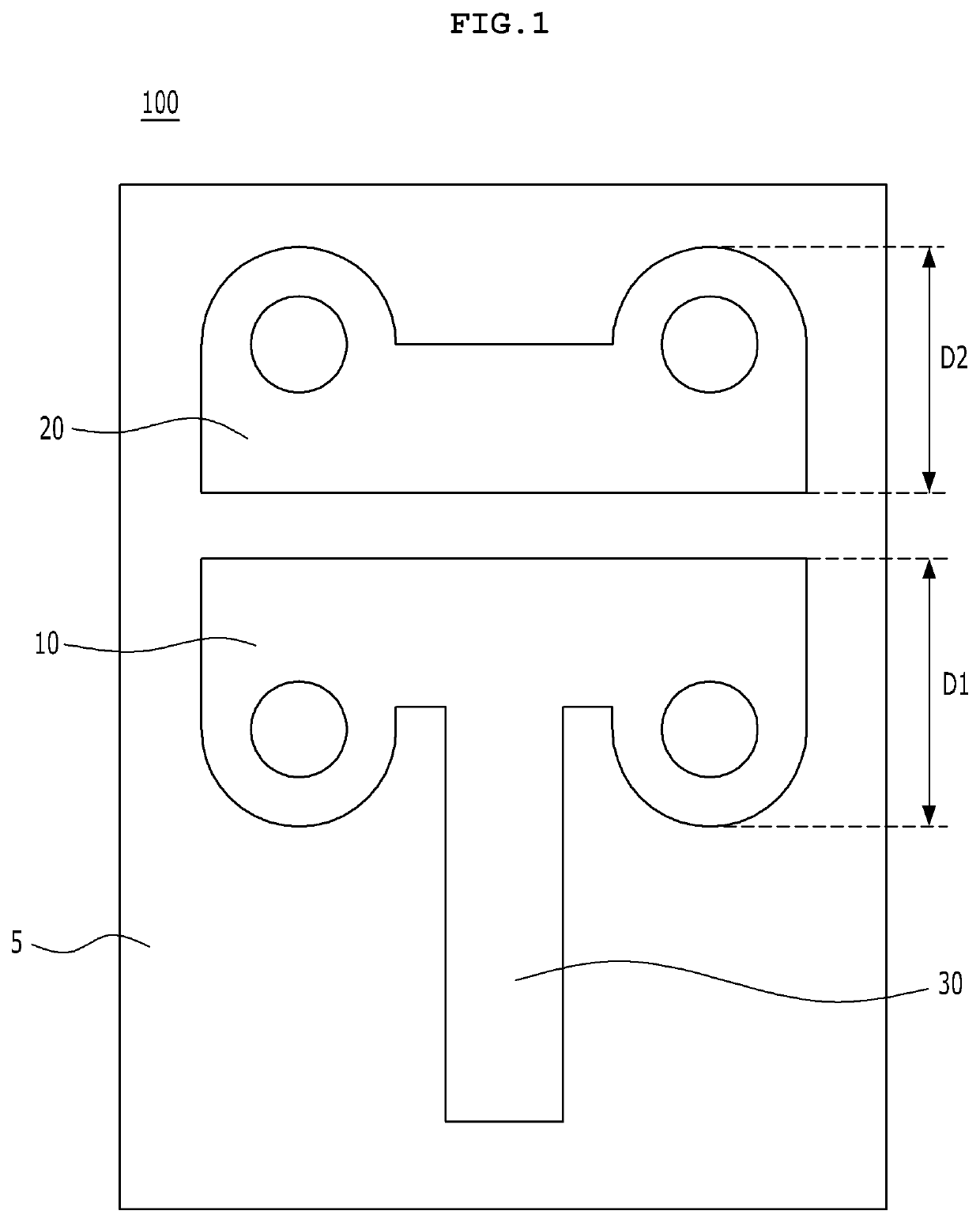
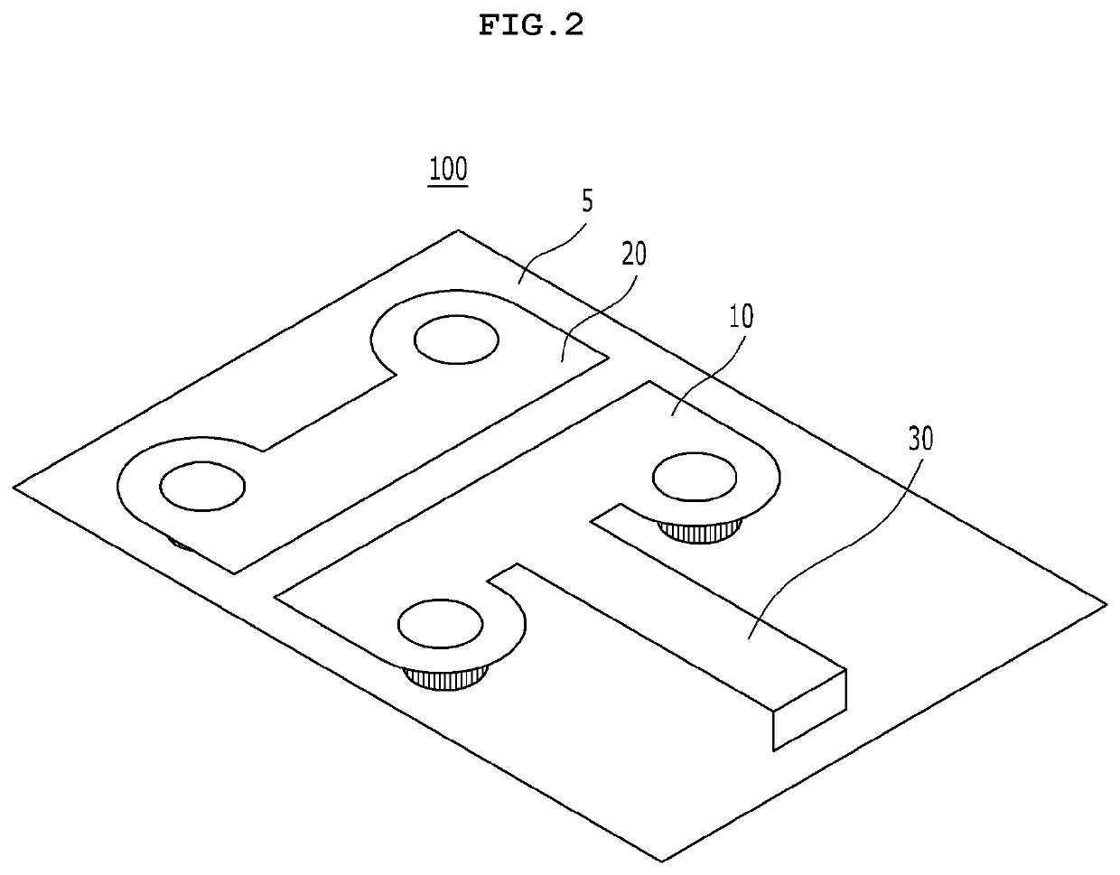
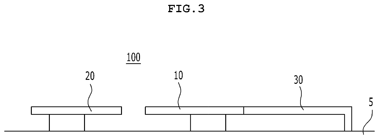
[0031]Advantages and features of the present invention, and a method to achieve them of the present invention will be obvious with reference to embodiments along with the accompanying drawings which are described below. Meanwhile, it will be understood that present description is not intended to limit the invention to those exemplary embodiments. On the contrary, the invention is intended to cover not only the exemplary embodiments, but also various alternatives, modifications, equivalents and other embodiments, which may be included within the spirit and scope of the invention as defined by the appended claims. In the detailed description, the same reference numbers of the drawings refer to the same or equivalent parts of the present invention.

[0032]Unless otherwise defined, all terms (including technical and scientific terms) used herein have the same meaning as commonly understood by one of ordinary skill in the art to which this disclosure belongs. It will be further understood ...


PUM


Abstract

A patch antenna includes: a substrate; a first radiator disposed on the substrate and having a first shape; a second radiator disposed on the substrate while being spaced a predetermined distance apart from the first radiator, and having a second shape; and a power feeder which supplies a power feed signal to the first radiator, wherein the first radiator includes a first outer edge portion straightly formed in the horizontal direction and second outer edge portions vertically formed from both ends of the first outer edge portion.

Description

TECHNICAL FIELD[0001]The present invention relates to a patch antenna and an array antenna having the same. More particularly, the present invention relates to a patch antenna and an array antenna having the same, which can be used as a radar for a vehicle since having a wide bandwidth and a wide beam width.BACKGROUND ART[0002]As an autonomous driving age has arrived, various kinds of sensors are mounted on vehicles, and a radar is one of such sensors.[0003]Meanwhile, there are various kinds of radars to be mounted on vehicles. The radars are divided into a long range radar (LRR), a middle range radar (MRR), and a short range radar (SRR). The SRR, more specifically, ultra short range radars (USRRs), are used for corner radars of passenger cars or used on the sides of trucks or buses.[0004]Such USRRs perform a blind spot detection (BSD) function to detect blind spots. Accordingly, the USRRs essentially require wide bandwidth and beam width, and more specifically, require a bandwidth ...

Claims


Application Information

Patent Timeline
14 Jul 2022
Publication
US20220224012A1
IPC
H01Q9/04; H01Q21/08
CPC
H01Q9/045; H01Q21/08; H01Q9/0421; H01Q19/005
Inventors
KIM, JEONG PYO