
Telescoping torch

Pending Publication Date: 2022-08-11
THE ESAB GROUP
View PDF0 Cites 0 Cited by
  • Summary
  • Abstract
  • Description
  • Claims
  • Application Information

AI Technical Summary

Benefits of technology

The present patent is about plasma arc torches that can be adjusted in length for different uses or applications. The torch can be adjusted by sliding the torch head housing along the torch body. The torch head housing can be locked in place to secure the torch at a desired length. The torch can also have a telescoping feature that allows for adjustment between a maximum and minimum length. The torch can be equipped with a longitudinal slot and a conductive contact to secure the torch at a specific position. The torch can also have a neck segment with notches that can be engaged with a lock ring to adjust the length. The torch can also have a longitudinally adjustable neck portion that is received by a conduit in the torch body. These features enable the torch to be adjusted to the desired length for a specific use or application.

Problems solved by technology

Current welding and plasma torches have a set length, and that length is typically not adjustable.
This may result in a user having to switch torches in the middle of a single job as the performance needs and desires of the torch change.
Because torches of different lengths may be required for a particular job or a particular task, the need to transport multiple torches of varying lengths results in added cost and space requirements.

Method used


Image

  • Telescoping torch
  • Telescoping torch
  • Telescoping torch

Examples


first embodiment

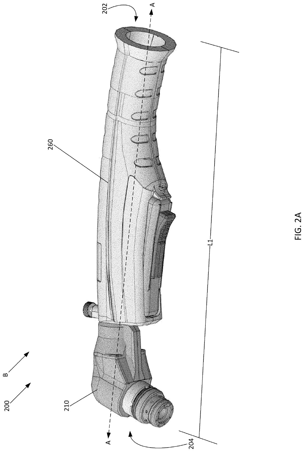
[0049]Turning to FIGS. 2A, 2B, 3, 4A, 4B, 5A, and 5B, illustrated is a telescoping torch 200. The torch 200 may include a first end 202 (e.g., the connection end) and an opposite second end 204 (e.g., the operating end). The torch 200 may include a torch head housing 210 and a torch body housing 260. The torch head housing 210 may be disposed more proximate to the second end 204 of the torch 200 than the first end 202 of the torch 200. Furthermore, the torch body housing 260 may be disposed more proximate to the first end 202 of the torch 200 than the second end 204 of the torch 200. As explained in further detail below, the torch head housing 210 may be configured to telescope or slide along longitudinal axis A of the torch 200 between at least a collapsed position B (FIG. 2A), where the torch head housing 210 may be fully telescoped into the torch body housing 260 and the torch may have a length L1, and an expanded position C (FIG. 2B), where the torch head housing 210 may be full...

third embodiment

[0079]As previously stated, the torch head housing 610 may be configured to telescope, or axially extend / contract, with respect to the torch body housing 640 in order to change / alter the length of the torch 600. As best illustrated in FIGS. 10A and 10B, the neck portion 620 may be slidably disposed within the interior cavity 650 of the torch body housing 640 by being inserted through the annular tabs 646 (e.g., such that the annular tabs 646 at least partially surround the neck portion 620) and the second end 644 of the torch body housing 640. More specifically, at least the first end 622 of the neck portion 620 is disposed within the interior cavity 650. When the torch 600 is in the fully collapsed configuration F, which is illustrated in FIGS. 8A and 10A, the first end 622 of the neck portion 620 of the torch head housing 610 is disposed within the interior cavity 650 more proximate to the first end 642 of the torch body housing 640 than the second end 644 of the torch body housin...


PUM

PropertyMeasurementUnit
Lengthaaaaaaaaaa
Forceaaaaaaaaaa
Flexibilityaaaaaaaaaa

Abstract

A torch having an adjustable length. The torch may include a first housing portion and a second housing portion. The second housing portion may be slidably coupled to the first housing portion. The second housing portion may be configured to slide along a longitudinal direction of the torch to adjust a length of the torch.

Description

CROSS-REFERENCE TO RELATED APPLICATIONS[0001]This application claims priority under 35 U.S.C. 119(e) to U.S. Provisional Patent Application Ser. No. 63 / 147,874, entitled “TELESCOPING TORCH”, filed February 10, 2021, the disclosure of which is incorporated herein by reference in its entirety for all purposes.TECHNICAL FIELD[0002]The present disclosure is directed toward welding and / or cutting torches and, in particular, to length adjustable welding and / or cutting torches.BACKGROUND OF THE INVENTION[0003]Current welding and plasma torches have a set length, and that length is typically not adjustable. Every torch length offers specific trade-offs to the user of the torch as there are advantages to both longer torches and shorter torches. For example, a longer torch may provide at least the following advantages: better visibility of the torch tip; better manual control due to the responsiveness of the torch resulting from a longer moment arm from the user's hands; improved reach; impro...

Claims


Application Information

Patent Timeline
IPC IPC(8): B23K10/00H05H1/34
CPCB23K10/00H05H1/34H05H1/3423H05H2245/60B23K10/02B23K9/287
Inventor MAYNARD, AUSTONNADLER, MICHAELSMITH, DOUGLAS
Owner THE ESAB GROUP
Learn More