Method and apparatus for indication of synchronization signal block
a synchronization signal and indication method technology, applied in the direction of synchronisation arrangement, orthogonal multiplex, multiplex communication, etc., can solve the problem that the method of configuring a synchronization block for the nr system has not been defined in detail
- Summary
- Abstract
- Description
- Claims
- Application Information
AI Technical Summary
Benefits of technology
Problems solved by technology
Method used
Image
Examples
embodiment 1
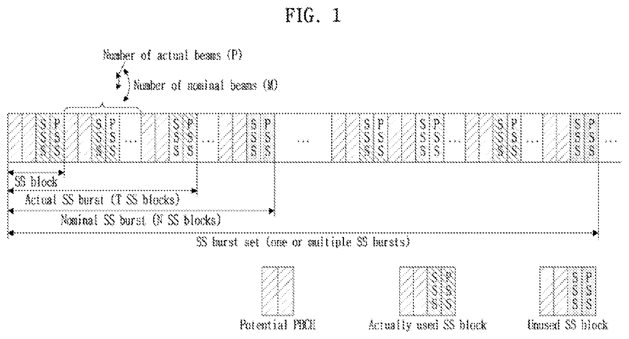
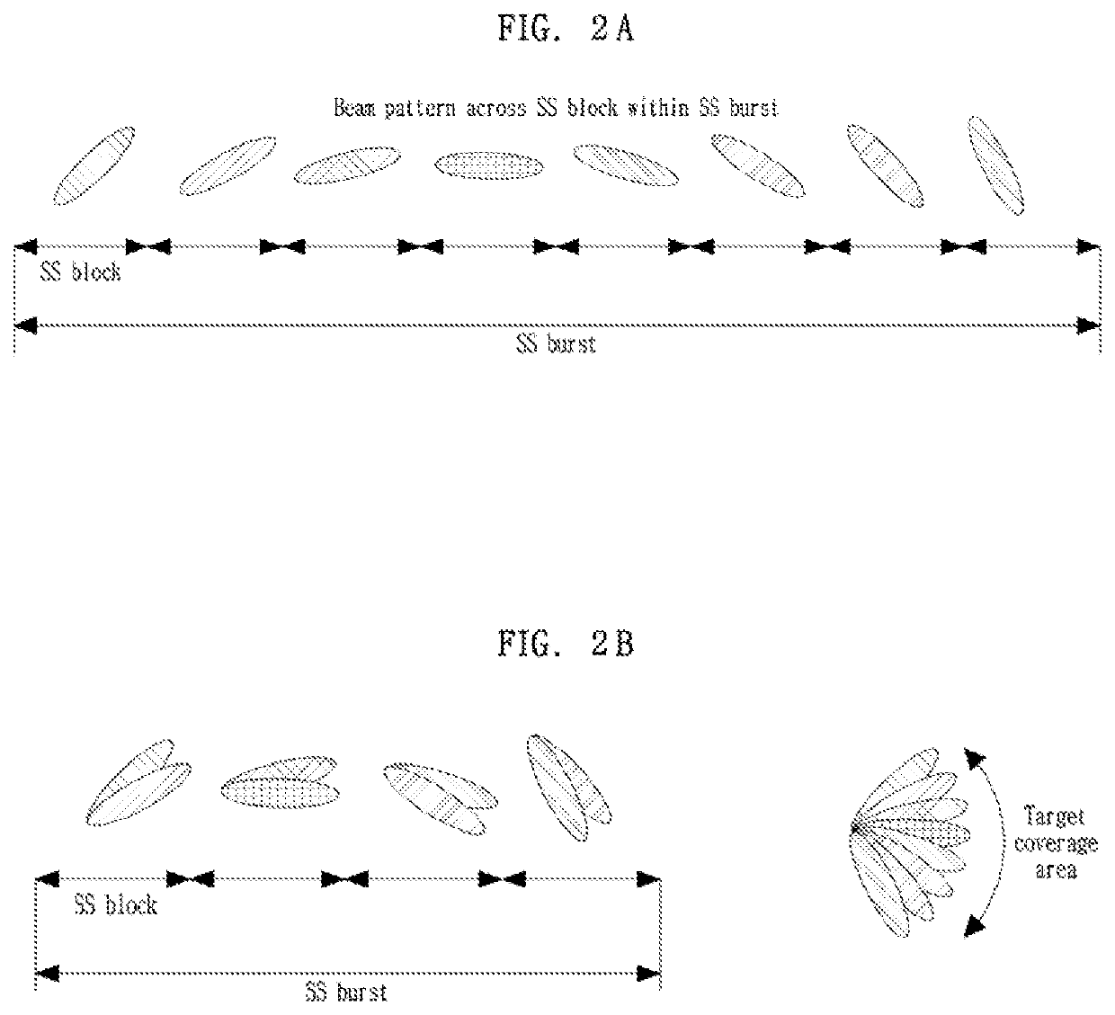
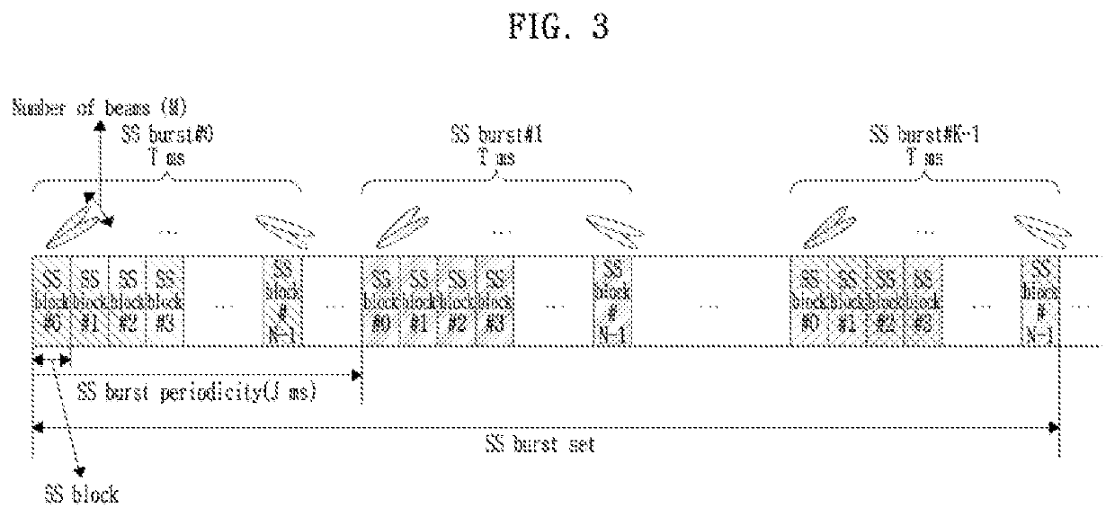
[0083]The present embodiment relates to a method of indicating an index of an actual transmission SS block using a bitmap. For example, the base station may provide the terminal with information indicating an actual transmission SS block among a set of a predetermined number (=L_base) of nominal SS blocks. For example, the set of the predetermined number of nominal SS blocks may be a set of nominal SS blocks included in a single SS burst set. Bitmap information indicating the actual transmission SS block may be defined and thereby used by using, as a unit, the set of the predetermined number of nominal SS blocks.
[0084]The bitmap information may relate to a bitmap that uses the set of the predetermined number of nominal SS blocks within the SS burst set as a unit, and may further include additional information that is described below. Through this, a time index of an SS block corresponding to a time location of the actual transmission SS block among the entire nominal SS blocks may b...
embodiment 1-1
[0086]The present embodiment relates to a method of using L_base bits of “bitmap for actual transmission SS block index” included in the RMSI or the NR-MIB transmitted through the NR-PBCH.
[0087]If the frequency range is less than or equal to 3 GHz, a maximum of four SS blocks (i.e., block index #0 to SS block index #3) may be present within a single SS burst set and 4 bits of “bitmap for actual transmission SS block index” may be defined based thereon. That is, the bitmap information may indicate an SS block that is actually used among the four SS blocks.
[0088]For example, if a bit value corresponding to an SS block among bit locations of a bitmap is 0, it indicates that the SS block is not an actual transmission SS block and if the bit value is 1, it may indicate that the SS block is the actual transmission SS block. Alternatively, if the bit value corresponding to the SS block among bit locations of the bitmap is 0, it may indicate that the SS block is the actual transmission SS b...
embodiment 1-2
[0093]The present embodiment relates to a method of using additional information to indicate a time index of an actual transmission SS block with respect to a set of nominal SS blocks greater than the size of the basic bitmap defined in the aforementioned embodiment 1-1. Here, the additional information may be information indicating an application pattern of the basic bitmap with respect to a specific basic SS block group.
[0094]For example, if the frequency range is less than or equal to 3 GHz, the terminal may be informed a time index of an SS block corresponding to a time location of an actual transmission SS block using a basic bitmap with an L_base bit size included in RMSI or an NR-MIB transmitted through an NR-PBCH.
[0095]If the frequency range is 3 GHz to 6 GHz, the terminal may be informed the time index of the SS block corresponding to the time location of the actual transmission SS block using the basic bitmap with the L_base bit size included in the RMSI or the NR-MIB tran...
PUM
 Abstract
Description
Claims
Application Information
 - R&D
- Intellectual Property
- Life Sciences
- Materials
- Tech Scout
- Unparalleled Data Quality
- Higher Quality Content
- 60% Fewer Hallucinations
Browse by: Latest US Patents, China's latest patents, Technical Efficacy Thesaurus, Application Domain, Technology Topic, Popular Technical Reports.
© 2025 PatSnap. All rights reserved.Legal|Privacy policy|Modern Slavery Act Transparency Statement|Sitemap|About US| Contact US: help@patsnap.com


