Method for detecting inconsistencies in the outputs of perception systems of autonomous vehicles

Pending Publication Date: 2022-09-29
IVEX
0 Cites 0 Cited by

AI-Extracted Technical Summary

Problems solved by technology

However, there is no quality assurance system for the observed information at runtime.
Hence, errors at perception systems can propagate to actions taken by the automated vehicles that can be cata...

Abstract

A system and method for the detection of inconsistencies in perception systems of autonomous vehicles is described. The system receives the observations of objects in the surrounding environment from one or more sensors or perception systems of an automated vehicle. At actual time, the system estimates the consistency of the currently observed elements of the perception system according to the previous inputs received. This consistency is decided by calculating the boundaries of possible states of the previously observed elements, based on the received information and on assumptions.

Application Domain

External condition input parameters

Technology Topic

Real-time computingPerception system +2

Image

  • Method for detecting inconsistencies in the outputs of perception systems of autonomous vehicles
  • Method for detecting inconsistencies in the outputs of perception systems of autonomous vehicles

Examples

  • Experimental program(1)

Example

DETAILED DESCRIPTION OF THE DRAWINGS
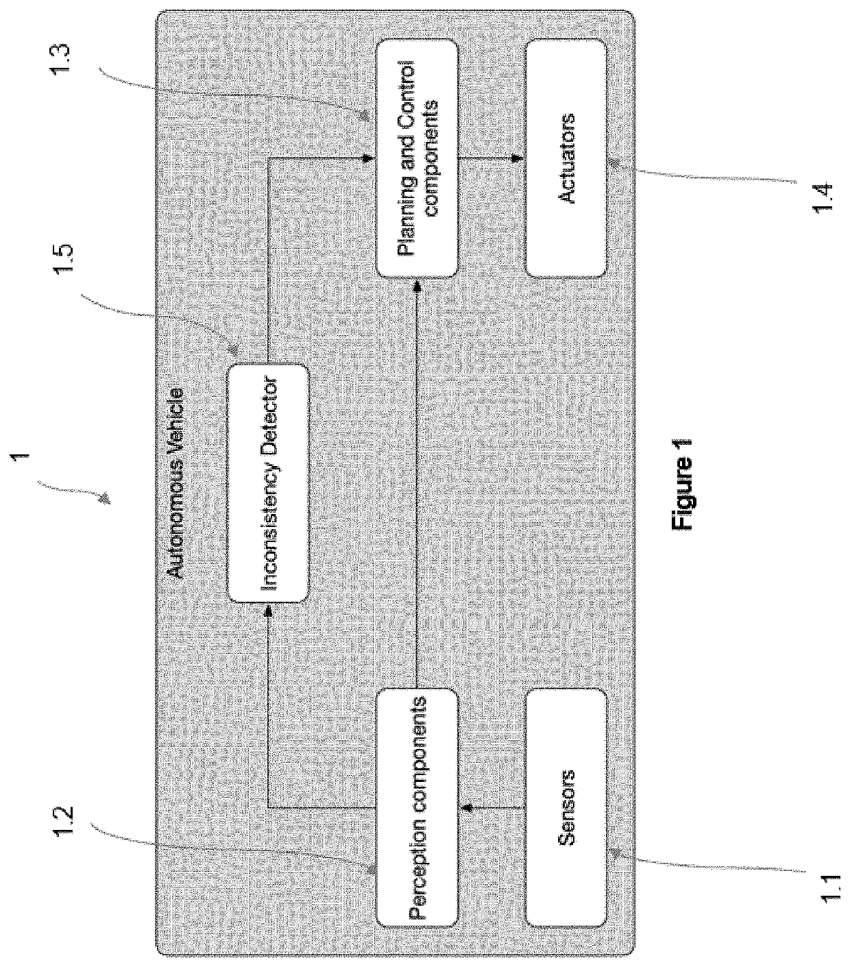
[0080]FIG. 1 is a schematic flow chart of the inconsistency detector system of the present invention in an autonomous vehicle system (1). The information from the environment measured by sensors (1.1) is directed to the perception systems (1.2) of the automated vehicle. Examples of sensors include: [0081] Cameras, [0082] Light Detection And Ranging, also referred to as LiDAR, [0083] Radars, or [0084] Global Navigation Satellite System positioning, also referred to as GNSS positioning.
[0085]The perception systems (1.2) of the vehicle interpret the raw information from the sensors (1.2) and extract observations on the scene. Such observations include one or more of the existing elements, their position, or environmental conditions.
[0086]The vehicle central board (1.3) is capable of performing several vehicle processes, such as vehicle control and decision making units that perform tasks such as path planning. The outputs of the vehicle central board (1.3) are executed by the vehicle actuators (1.4).
[0087]The inconsistency detector system (1.5) of the present invention monitors information from the sensors (1.1) and the perception systems (1.2), hereinafter jointly referred to as observations. The inconsistency detector system (1.5) informs the vehicle central board (1.3) about the reliability of those observations.
[0088]The system is running on an electronic control unit including one or more processors and a memory. The memory may include one or more instructions which can be executed by one or more processors causing the detection of inconsistencies from the input observations received at the electronic control unit.
[0089]The system receives observations of the scene and objects in the surrounding environment from one or more sensors (1.1) or from one or more perception systems (1.2) in the vehicle. The system may receive additional input from road information such as shape of the road, curvature, traffic status, or surface condition or a combination thereof. The system may also receive additional input such as environmental conditions including the position of the sun, weather, or humidity.
[0090]In another embodiment, the system receives the observations at a single time or during an interval comprising consecutive times.
In another embodiment, the system receives previously stated input, observations and times.
[0091]In general, each observation obtained from the real scene observed by the sensors (1.1) or the perception systems (1.2) generates one or several observation states in the inconsistency system associated to a time. Each observed state is stored for a fixed period of time. For example, an observed state may be stored for 2 seconds.
[0092]In subsequent times, the current observed state system inputs are updated to estimated states. The estimated states are obtained by calculating the boundaries of the possible states of the objects or the scene, hereinafter referred to as state boundaries.
[0093]The calculation of the state boundaries is based on one or more of the following parameters and features: [0094] the previously received observations, [0095] the assumptions on the behavior or aspect of the object, and [0096] the road information and environmental conditions received.
[0097]Once the current observations are received, the inconsistency detection system (1.5) evaluates their consistency as shown in FIG. 2.
[0098]In a first step, the inconsistency detector system (1.5) checks for each new observed state, whether there exists previously stored estimated states of the same object or scene.
[0099]If there are no previously stored estimated states of the same object or full or partial scene, the system does not perform an inconsistency check.
[0100]If there are previously stored estimated states of the same object or full or partial scene, the system performs an inconsistency check. The inconsistency check consists of assessing whether or not the current observed state lies in the estimated state boundaries. If the new observed state is outside of the calculated boundaries, the inconsistency detection system (1.5) will consider the output of the perception system (1.2) or of the sensors (1.1) as inconsistent.
[0101]If an inconsistency is detected, the inconsistency detection system sends a notification to the control units in the vehicle to act accordingly and safely. With this signalization, the control units can perform appropriate actions to mitigate the inconsistency such as informing other subsequent systems as for example systems responsible for planning, decision making and control on the autonomous vehicle.
[0102]In one embodiment, the actions taken by the control system (1.4) that receives the inconsistency system signals of sensor or perception inconsistencies are not under the scope of this invention.
TABLE 1 English expressions used in the drawings for translation purposes: Autonomous vehicle Autonoom voertuig Sensor Sensor Perception component Perceptie-element Inconsistency detector Inconsistentiedetector Planning and control components Onderdelen voor planning en regeling Actuators Actuatoren Receive a new observation Ontvang een nieuwe waarneming Check if there exists previous Controleer of er eerdere observations of the same object waarnemingen van hetzelfde object bestaan Yes Ja No Nee Exit Exit Calculate boundaries from each Bereken de grenzen van iedere previous observation voorgaande waarneming Check whether the new Controleer of de nieuwe waarneming observation stays inside binnen alle grenzen blijft all boundaries Notify other systems about the Informeer andere systemen over de inconsistency inconsistentie

PUM

no PUM

Description & Claims & Application Information

We can also present the details of the Description, Claims and Application information to help users get a comprehensive understanding of the technical details of the patent, such as background art, summary of invention, brief description of drawings, description of embodiments, and other original content. On the other hand, users can also determine the specific scope of protection of the technology through the list of claims; as well as understand the changes in the life cycle of the technology with the presentation of the patent timeline. Login to view more.
Why Eureka
Try Eureka