Eureka AIR delivers breakthrough ideas for toughest innovation challenges, trusted by R&D personnel around the world.

Controller for ac rotary machine

Pending Publication Date: 2022-10-27
MITSUBISHI ELECTRIC CORP
View PDF0 Cites 0 Cited by
  • Summary
  • Abstract
  • Description
  • Claims
  • Application Information

AI Technical Summary

Benefits of technology

The patent text discusses a new technology that allows for faster and more efficient data processing. The technology uses a special material called a photonic crystal, which helps to transmit light signals more effectively. This means that data can be processed more quickly and with less delay. Overall, this technology can improve the performance and speed of data processing systems.

Problems solved by technology

Since the motor current always flows into both current detection circuits, it is difficult to obtain offset of current detection on-line.

Method used


Image

  • Controller for ac rotary machine
  • Controller for ac rotary machine
  • Controller for ac rotary machine

Examples


embodiment 1

1. Embodiment 1

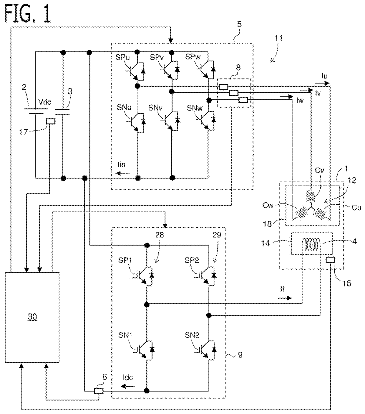
[0031]A controller for AC rotary machine 11 (hereinafter, referred to simply as the controller 11) according to Embodiment 1 will be explained with reference to drawings. FIG. 1 is a schematic configuration diagram of the AC rotary machine 1 and the controller 11 according to the present embodiment.

1-1. AC Rotary Machine

[0032]The AC rotary machine 1 is provided with a stator 18 and a rotor 14 disposed on the radial-direction inner side of the stator 18. The AC rotary machine 1 is a field winding type synchronous rotary machine. An AC armature winding 12 is wound around the stator 18. A field winding 4 is wound around the rotor 14, and is provided with an electromagnet.

[0033]In the present embodiment, the AC armature winding 12 is three-phase AC armature windings Cu, Cv, Cw of U phase, V phase, and W phase. The three-phase AC armature windings Cu, Cv, Cw may be by a star connection, or may be by a delta connection.

[0034]An angle detection circuit 15 which detects a rot...

embodiment 2

2. Embodiment 2

[0082]Next, the AC rotary machine 1 and the controller 11 according to Embodiment 2 will be explained. The explanation for constituent parts the same as those in Embodiment 1 will be omitted. The basic configuration of the AC rotary machine 1 and the controller 11 according to the present embodiment is the same as that of Embodiment 1. However, Embodiment 2 is different from Embodiment 1 in the configuration of the bus current detection circuit 6 and the processing using the output signal of the bus current detection circuit 6. FIG. 11 is a schematic configuration diagram of the AC rotary machine 1 and the controller 11 according to the present embodiment.

[0083]In the present embodiment, the bus current detection circuit 6 is provided with one current detector 13, and a plurality of signal processors each of which process an output signal of the current detector 13 and outputs a process signal to the control device 30 (the current calculation unit 32). As the pluralit...

embodiment 3

3. Embodiment 3

[0090]Next, the AC rotary machine 1 and the controller 11 according to Embodiment 3 will be explained. The explanation for constituent parts the same as those in Embodiment 1 will be omitted. The basic configuration of the AC rotary machine 1 and the controller 11 according to the present embodiment is the same as that of Embodiment 1. However, Embodiment 3 is different from Embodiment 1 in the configuration of the bus current detection circuit 6 and the processing using the output signal of the bus current detection circuit 6. FIG. 12 is a schematic configuration diagram of the AC rotary machine 1 and the controller 11 according to the present embodiment.

[0091]In the present embodiment, the connection path between DC power source 2 and the converter 9 is provided with a plurality of parallel connection path parts which branch into plurality and are arranged in parallel. Then, the bus current detection circuit 6 is provided with a plurality of current detectors each o...


PUM


Abstract

To provide a controller for AC rotary machine which can detect the field current flowing through the field winding with good accuracy and can suppress the heat generation of the current detection circuit. A controller for AC rotary machine is provided with a bus current detection circuit that detects a bus current which flows through a connection path between a DC power source and a converter; a converter switching control unit that switches a power supply path and a circulation path of the converter; and a current calculation unit that calculates a field current flowing into the field winding, based on a bus current in suppling power detected when switching to the power supply path and a bus current in circulating detected when switching to the circulation path.

Description

TECHNICAL FIELD[0001]The present disclosure relates to a controller for AC rotary machine.BACKGROUND ART[0002]The electronic control unit of PLT 1 drives the DC motor by the H bridge circuit, and detects the motor current using the first current detection circuit and the second current detection circuit. Abnormality is determined by mutually comparing the signal of first current detection circuit and the signal of second current detection circuit. Since the motor current always flows into both current detection circuits, it is difficult to obtain offset of current detection on-line.[0003]The electric power steering apparatus of PLT 2 drives the DC motor by H bridge circuit, and using the shunt resistance provided in series on the bus line which connects the DC power source and the H bridge circuit, detects the motor current by detecting the bus current two times in the PWM period for controlling on / off the H bridge circuit.CITATION LISTPatent Literature[0004]PLT 1: JP 2018-182798 A[...

Claims


Application Information

Patent Timeline
IPC IPC(8): H02P27/08H02P25/022H02M1/00G01R19/10G01R35/00
CPCH02P27/08H02P25/022H02M1/0009G01R19/10G01R35/00H02P25/03H02P9/305
Inventor FURUKAWA, AKIRA
Owner MITSUBISHI ELECTRIC CORP
Why Eureka
Eureka Blog
Learn More