Electromagnetic valve drive device

Active Publication Date: 2020-04-02
HITACHI ASTEMO LTD
View PDF0 Cites 1 Cited by
  • Summary
  • Abstract
  • Description
  • Claims
  • Application Information

AI Technical Summary

Benefits of technology

The patent text describes an electromagnetic valve drive device that reduces heat generation during synchronous rectification control. The technical effect is to improve the efficiency of the device and prevent overheating.

Problems solved by technology

However, when the resolution of time setting of the timer is low, it is necessary to set the dead time period to be longer than necessary from the viewpoint of safety.
As a result, the time for which the energy accumulated in the inductor is supplied to the output capacitor via the diode becomes longer, and it is not possible to improve the effect on the loss reduction of the diode due to the execution of the synchronous rectification control.

Method used


Image

  • Electromagnetic valve drive device
  • Electromagnetic valve drive device
  • Electromagnetic valve drive device

Examples


Embodiment Construction

[0019]Hereinafter, a fuel injection valve drive device according to an embodiment of the present invention will be described using drawings.

[0020]A fuel injection valve drive device A according to the present embodiment is a drive device that drives a fuel injection valve L. That is, the fuel injection valve drive device A according to the present embodiment is an electromagnetic valve drive device that drives the fuel injection valve L (an electromagnetic valve) that injects fuel to an internal combustion engine mounted on a vehicle.

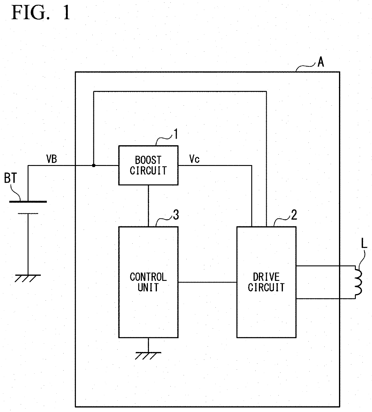
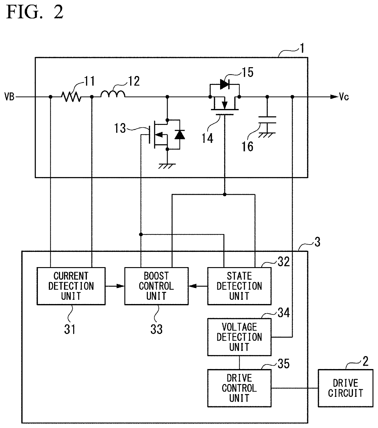
[0021]As illustrated in FIG. 1, the fuel injection valve drive device A includes a boost circuit 1, a drive circuit 2, and a control unit 3.

[0022]The boost circuit 1 is a chopper circuit capable of executing a boosting operation for boosting a battery voltage VB that is input from a battery BT mounted on a vehicle to a predetermined target voltage (a boosted voltage Vc). The boost circuit 1 generates a predetermined boosted voltage Vc from the battery v...


PUM


Abstract

An electromagnetic valve drive device includes: a state detection unit configured to detect an on-state or an off-state of a first switch and a second switch forming a boosting circuit; a boosting control unit configured to control a boosting operation, by performing a synchronous rectification control on switching of the first switch and the second switch, depending on the state of the first switch or the second switch detected by the state detection unit; and a drive circuit configured to drive an electromagnetic valve by supplying a voltage boosted by the boosting operation to the electromagnetic valve.

Description

CROSS-REFERENCE TO RELATED APPLICATION[0001]The present application claims priority under 35 U.S.C. § 119 to Japanese Patent Application No. 2018-181629, filed on Sep. 27, 2018, the content of which is incorporated herein by reference.BACKGROUND OF THE INVENTIONField of the Invention[0002]The present invention relates to an electromagnetic valve drive device.Description of Related Art[0003]Japanese Unexamined Patent Application, First Publication No. 2012-158985A discloses a fuel injection valve drive device which opens a fuel injection valve, by boosting a voltage of a battery (hereinafter referred to as a “battery voltage”) by a boost circuit, and supplying the boosted voltage (hereinafter referred to as an “output voltage”) to the fuel injection valve.[0004]The boost circuit is configured to include an inductor, a first switch, a second switch, a diode, and an output capacitor. More specifically, one end of the inductor is connected to a battery power supply, and the other end th...

Claims


Application Information

Patent Timeline
IPC IPC(8): F01L9/04F02D41/20F01L9/20
CPCF01L9/04F02D2041/2006F02D41/20F16K31/06H02M3/156F02D2041/2058F02D2041/2075F02D2041/201F02D2041/2003F02D2041/2068F01L9/20
Inventor OGAWA, ATSUSHIKATO, MOTOAKINOMURA, KENGO
Owner HITACHI ASTEMO LTD
Why Eureka
Try Eureka