Eureka AIR delivers breakthrough ideas for toughest innovation challenges, trusted by R&D personnel around the world.

Vehicle brake device

Inactive Publication Date: 2006-07-13
HONDA MOTOR CO LTD
View PDF6 Cites 4 Cited by
  • Summary
  • Abstract
  • Description
  • Claims
  • Application Information

AI Technical Summary

Benefits of technology

[0009] The invention was made in view of the situations and an object thereof is to provide a vehicle brake device which can suppress the heat generation of the normally opened control valves even in the event that the parking brake is held in the applied state for many hours to thereby avoid the enlargement of the normally opened control valves and the drive circuit to enable a reduction in costs.

Problems solved by technology

In such a short-time rating type normally opened control valve, the value of current flowing through the coil provided in the normally opened control valve becomes high, which is thermally disadvantageous, and the thermal capacity of a drive circuit such as a field-effect transistor (FET) which controls the opening of the normally opened control valve has to be set relatively large.
Due to this, in the brake system in which the normally opened control valves are kept closed for many hours in order to hold the parking brake in the applied state, the normally opened control valves become thermally less advantageous, and this calls for enlargement in size of the normally opened control valves and the drive circuit, resulting in an increase in costs.

Method used


Image

  • Vehicle brake device
  • Vehicle brake device
  • Vehicle brake device

Examples


Embodiment Construction

[0061] Hereinafter, a mode for carrying out the invention will be described based on an embodiment of the invention shown in the accompanying drawings.

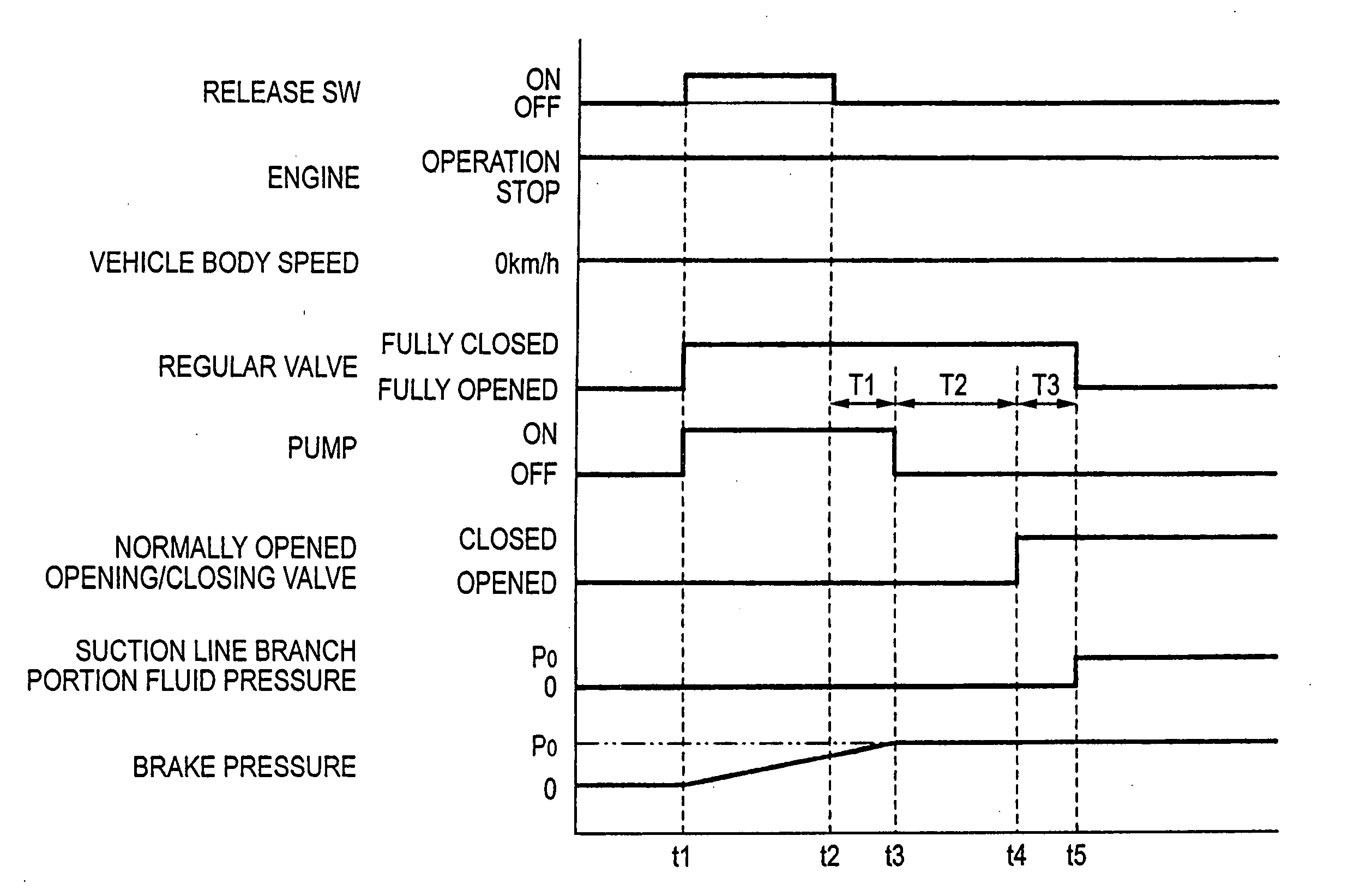
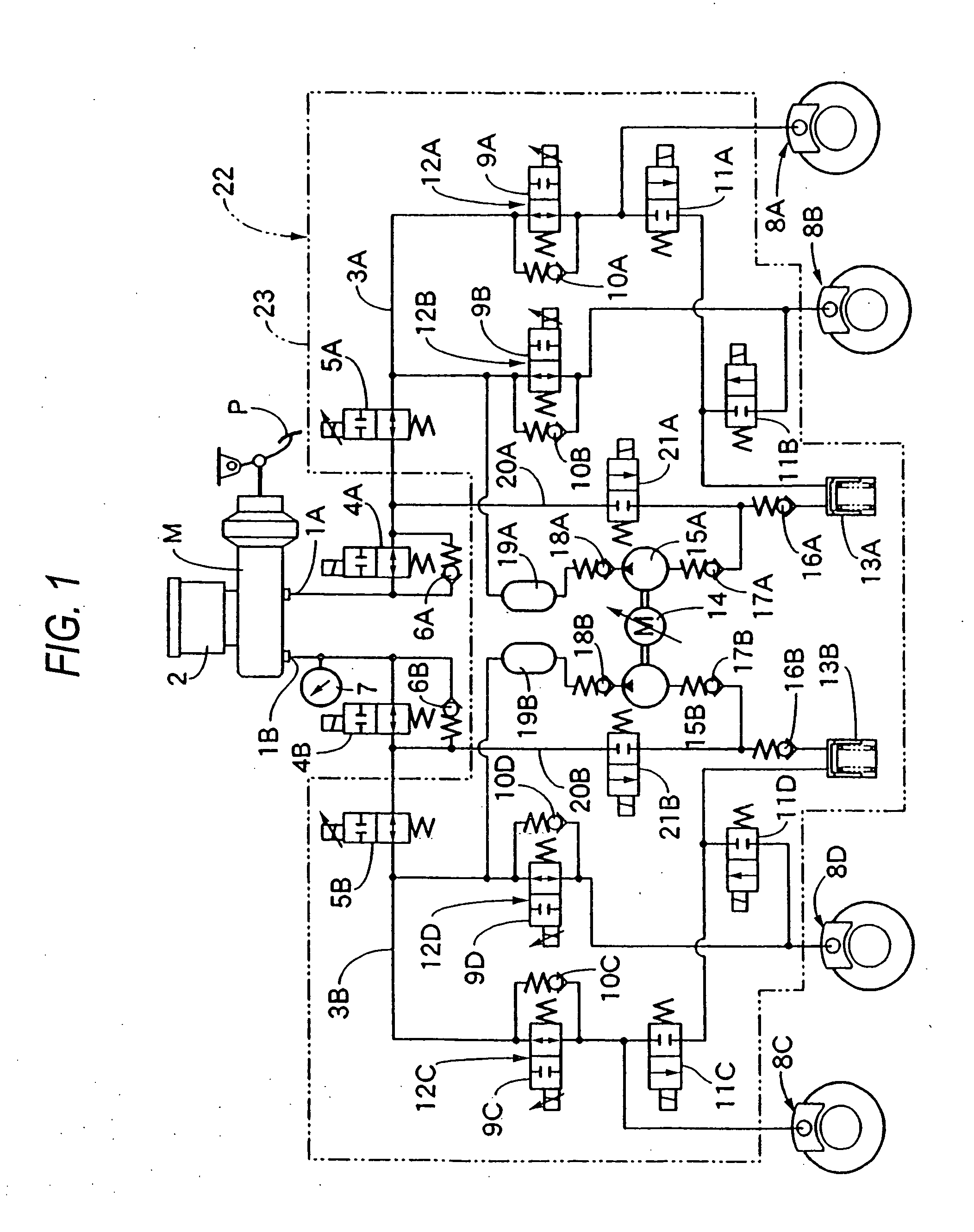
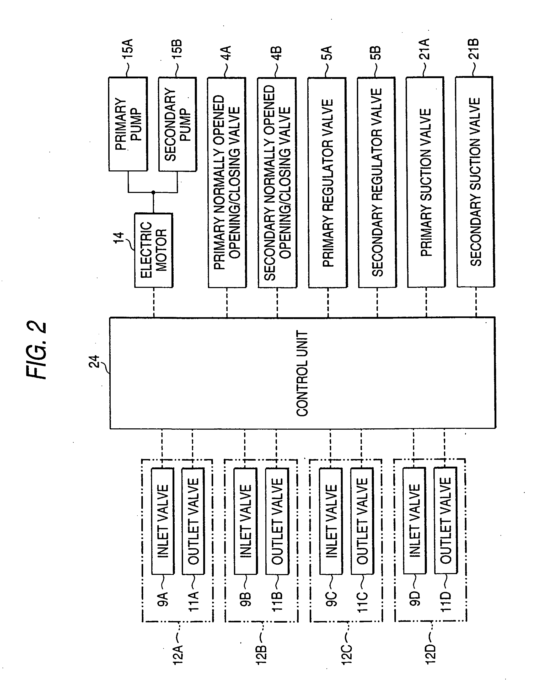
[0062] FIGS. 1 to 4 are such as to show an embodiment of the invention, in which FIG. 1 is a hydraulic circuit diagram of a vehicle brake device, FIG. 2 is a block diagram which shows the configuration of a control system, FIG. 3 is a timing chart resulting when a parking brake is in operation, and FIG. 4 is a timing chart resulting when the parking brake is released.

[0063] Firstly, in FIG. 1, a tandem master cylinder M, which is a fluid pressure generating device for generating a brake fluid pressure in accordance with an amount in which brakes are applied or a pedal effort applied to a brake pedal P by the driver of a vehicle, includes primary and secondary output ports 1A, 1B.

[0064] A primary normally opened opening / closing valve 4A, which is electrically controlled to open and close, and a primary regulator valve 5A, which is a...


PUM


Abstract

Normally opened control valves 5A, 5B are configured into short-time rating valves, and normally opened opening / closing valves 4A, 4B, which are electrically controlled to open and close and are configured into long-time rating valves, are connected in series to the normally opened control valves 5A, 5B between a fluid pressure generating unit M and wheel brakes 8A to 8D.

Description

[0001] The present invention claims foreign priority to Japanese patent application No. 2005-006543, filed on Jan. 13, 2005, the contents of which is incorporated herein by reference. BACKGROUND OF THE INVENTION [0002] 1. Field of the Invention [0003] The present invention relates to a vehicle brake device in which normally opened control valves which are electrically controlled in such a manner as not only to be changed over between a fully opened state and a fully closed state but also to obtain a half opened state between the fully opened and closed states are interposed between a fluid pressure generating unit which generates a fluid pressure in accordance with an operation amount and wheel brakes which are mounted on road wheels. [0004] 2. Description of the Background Art [0005] A vehicle brake device is known in, for example, Japanese Patent Unexamined Publication No. JP-A-2001-47988 in which normally opened control valves or proportional solenoid valves which are electricall...

Claims


Application Information

Patent Timeline
IPC IPC(8): B60T8/36
CPCB60T7/12B60T8/32B60T8/3655B60T8/4872
Inventor INAGAKI, HIROMIARIKAWA, YASUHIROKOBORI, HIDETOSHI
Owner HONDA MOTOR CO LTD
Why Eureka
Eureka Blog
Learn More