Gun sight system for a military vehicle

a technology for military vehicles and sight systems, applied in the field of housing for gun sight systems, can solve the problems of requiring a new sight system, affecting the use of weapons,

Inactive Publication Date: 2000-01-11
HANGER SOLUTIONS LLC +1
View PDF7 Cites 53 Cited by
  • Summary
  • Abstract
  • Description
  • Claims
  • Application Information

AI Technical Summary

Problems solved by technology

A problem has been encountered in that the new sight system is required to fit within the confines of an existing M1A2 tank.
Problems have been encountered with the existing sight system when it is removed from the tank for maintenance, repair or replacement.
There are also problems with the existing housing in relation to the ease by which a gunner is able to operate the controls of the sight system.
Again, these problems are caused by the confined spaces within a crew compartment and also by the stress induced by combat.
Also, the sighting system is a very complicated and sophisticated instrument which must

Method used


Image

  • Gun sight system for a military vehicle
  • Gun sight system for a military vehicle
  • Gun sight system for a military vehicle

Examples


Embodiment Construction

Illustrative embodiments and exemplary applications will now be described with reference to the accompanying drawings to disclose the advantageous teachings of the present invention.

While the present invention is described herein with reference to illustrative embodiments for particular applications, it should be understood that the invention is not limited thereto. Those having ordinary skill in the art and access to the teachings provided herein will recognize additional modifications, applications and embodiments within the scope thereof and additional fields in which the present invention would be of significant utility.

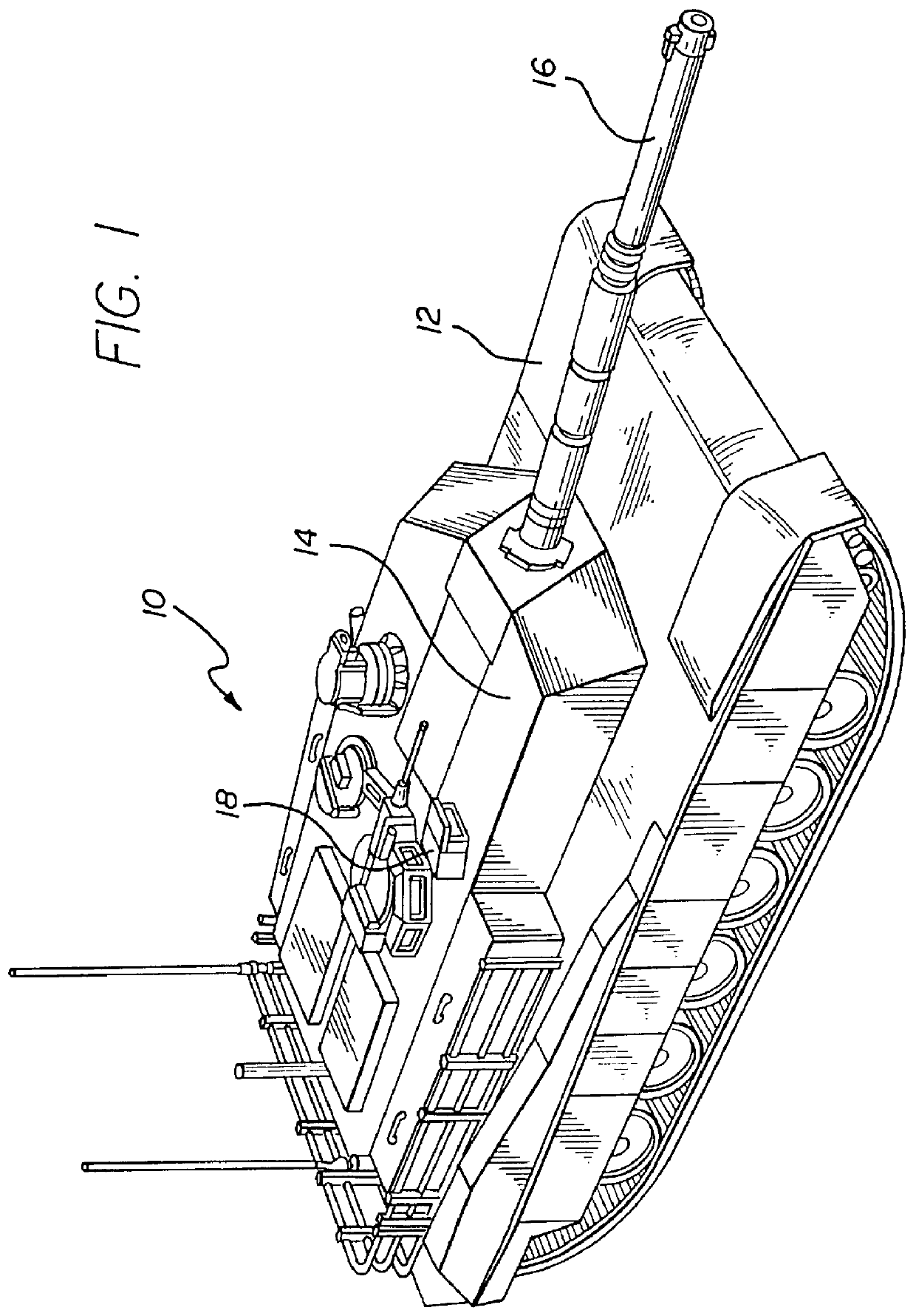
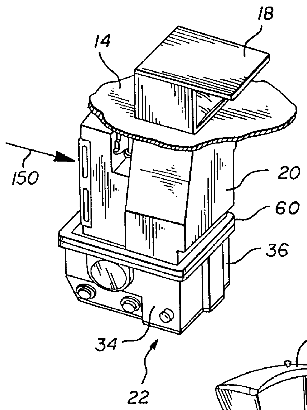
Referring now to FIG. 1 there is illustrated an M1A2 Abrams Main Battle tank 10 comprising a hull 12 to which is mounted a rotatable turret 14. Mounted to the turret is an M256 120 mm main gun 16. Among other things projecting from the top of the turret is an external viewing port 18 through which a gunner seated inside the turret is able to sight the main gun. M...


PUM


Abstract

An optical gun sight system for an M1A2 Abrams Main Battle Tank supported in a lower housing which may be attached to the fixed internal upper housing in the turret of the tank. An adapter plate is provided which has two sets of openings, one to align with the openings in the upper housing and the other to align with openings in the lower housing. An alignment mechanism allows for fine adjustment of the lower housing relative to the upper housing. Operating buttons, knobs and filter wheel are conveniently located on or beneath the front face of the lower housing. A thermal imaging system includes an objective lens for receiving an image of a target object, an eyepiece lens for viewing the image of the object, and a compensator lens movably located between the objective and eyepiece lenses for providing a thermal image of the object. The system includes a servo motor control system for controlling the position of the compensator lens based upon temperature, range and field of view to provide an accurate thermal image of the object.

Description

1. Field of the InventionThe present invention relates to a housing for a gun sight system, and more particularly to a housing for mounting an improved thermal imaging system which is especially designed to fit within the U.S. Army's M1A2 Main Battle Tank and other combat vehicles with little or no alteration.2. Description of the Related ArtThe M1A2 Abrams Main Battle Tank uses a thermal imaging gun sight system to control a 120 mm main gun. The conventional sight system operates in two modes through a lens system, one mode to be used in day time and the other mode to be used at night or when the battlefield is obscured. It was found during the fighting in and around Iraq in 1991, popularly referred to as "Desert Storm", that there was a need for increased performance of the gun sight system to allow improved targeting at greater distances. With a range of 3500 yards for the main gun, it can be appreciated that the need for a high performance gun sight system is substantial.A new t...

Claims


Application Information

Patent Timeline
IPC IPC(8): F41G3/22F41G3/00
CPCF41G3/22
Inventor HANKE, DIETMAR H.HULL, DAVID A.SMITH, RICHARD R.
Owner HANGER SOLUTIONS LLC
Why Eureka
Try Eureka