Surgical saw blade

a saw blade and surgical technology, applied in the field of surgical saw blades, can solve the problems of increased fatigue of surgeons, increased fatigue of saws, and increased tendency of saws to "kick"

Inactive Publication Date: 2000-02-08
SYNVASIVE TECH
View PDF8 Cites 137 Cited by
  • Summary
  • Abstract
  • Description
  • Claims
  • Application Information

AI Technical Summary

Benefits of technology

Accordingly, it is the primary object of the present invention to

Problems solved by technology

One of the most vexing problems that surgeons face when using surgical bone saws is the tendency of the saw to "kick" i.e., become caught upon the bone being cut by the point of the saw tooth.
This kicking or grabbing that occurs causes a loss of accuracy in the cut from the sudden, unpredictable movements of the saw and induces increased fatigue of the surgeon because of the greater tension that the surgeon must maintain in his hands and arms in anticipation of receiving this kicking or grabbing motion.
Another problem noted in existing blades involves the tendency of the saw to initially wander rather than to form a kerf.
With several teet

Method used


Image

  • Surgical saw blade
  • Surgical saw blade
  • Surgical saw blade

Examples


Embodiment Construction

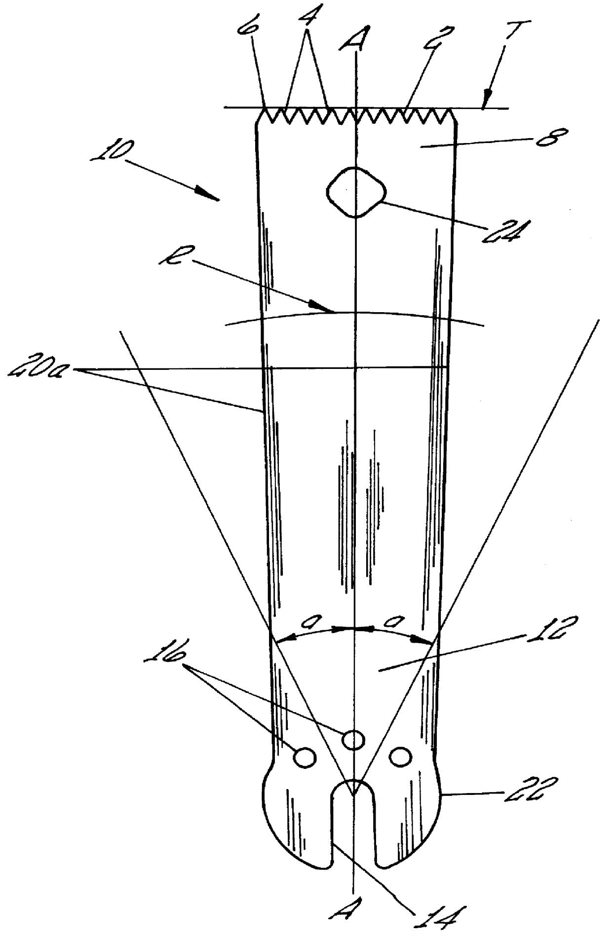
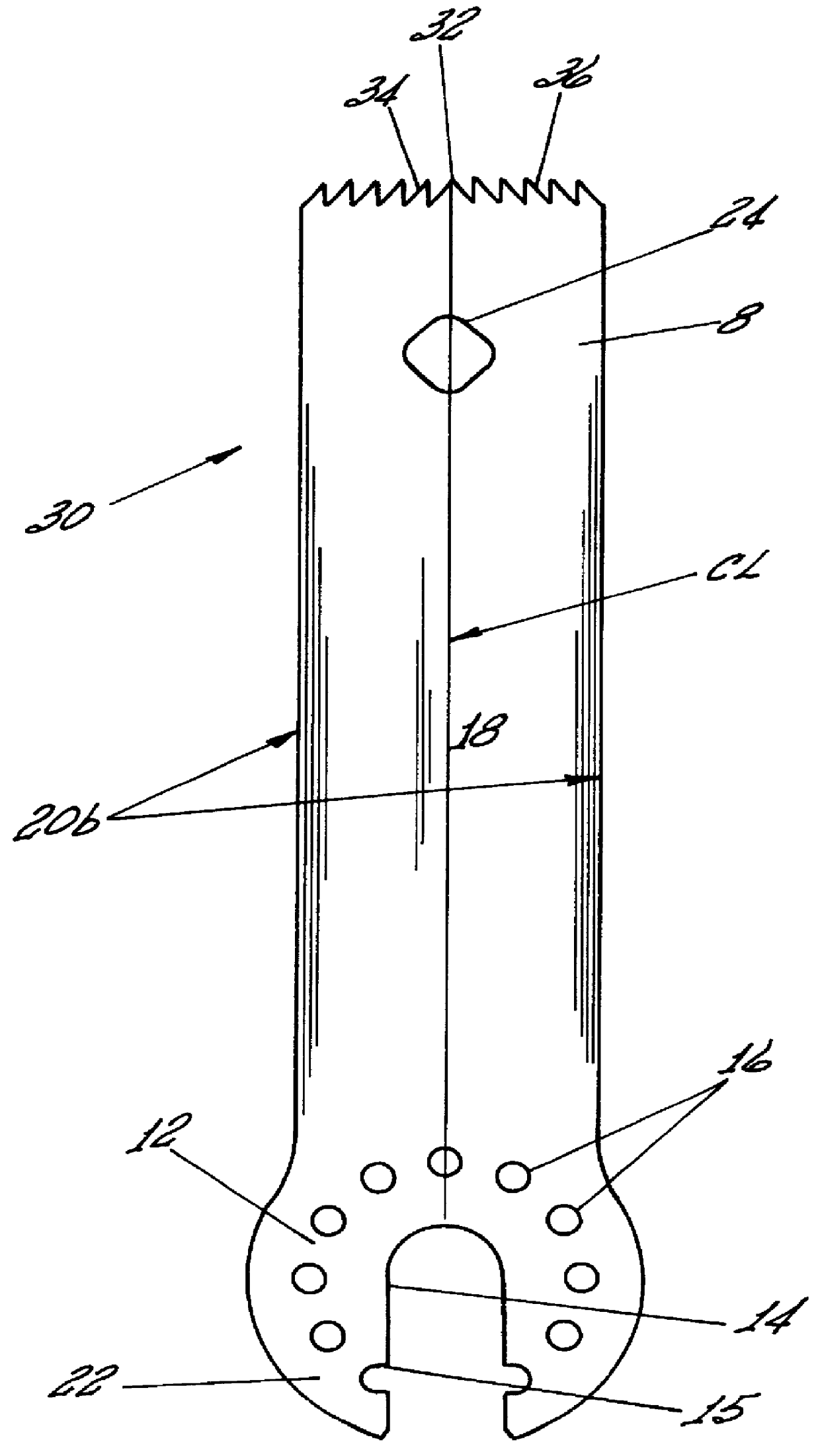
Referring now to the figures, wherein like reference numerals denote to like parts throughout the various figures, reference numeral 10 is directed to the straight saw blade according to one form of the invention, reference numeral 30 is directed to the reverse opposed blade according to the second form of the invention and reference numeral 40 is directed to the outwardly opposed blade according to a third form of the invention.

The straight saw blade 10 of FIG. 1 and according to the present invention includes a distal end 8 upon which a plurality of teeth 2 are positioned and a proximal end 12 which is adapted to coact with and attach to an oscillatory (or sagittal) surgical power tool (not shown).

More specifically, the proximal end 12 has a somewhat bulbous terminus 22 that includes a slot 14 running along the long axis A of the saw blade 10. In addition, a plurality of holes 16 circumscribe portions of the slot adjacent the bulbous terminus 22 to further facilitate interconnecti...


PUM

PropertyMeasurementUnit
Angleaaaaaaaaaa

Abstract

A cutting saw blade for use with an oscillatory power tool used in surgical bone cutting procedures including a blade having a distal end provided with teeth whose tips are located on a tangent line perpendicular to the long axis of the blade. The teeth are configured substantially as right triangles with their hypotenuses facing either towards the center of the blade or away from the center of the blade. A central tooth can be optionally provided.

Description

The following invention relates generally to instrumentalities for cutting bone during surgery. More particularly, the instant invention is directed to a saw blade adapted to be operatively coupled to an oscillatory (or sagittal) surgical power tool which reciprocates the cutting blade back and forth about a small arc.One of the most vexing problems that surgeons face when using surgical bone saws is the tendency of the saw to "kick" i.e., become caught upon the bone being cut by the point of the saw tooth. Another form of kicking occurs where the kerf has the same contour as the blade which is due to the fact that the cutting surface (i.e., teeth) lies on the same radius as the radius of tool rotation. In this scenario, all teeth grab nearly at the same time. This causes the saw apparatus to rotate about that point, transmitting a rotational force back through the saw and to the surgeon. This kicking or grabbing that occurs causes a loss of accuracy in the cut from the sudden, unpr...

Claims


Application Information

Patent Timeline
IPC IPC(8): A61B17/14B23D51/10B23D61/00B23D61/12B23D51/00B27B19/00
CPCA61B17/14B23D51/10B23D61/006B23D61/121B27B19/006A61B17/148A61B17/141A61B17/142
Inventor FLETCHER, HENRY HASBROUCKFISHER, MICHAEL GERARD
Owner SYNVASIVE TECH
Why Eureka
Try Eureka