Sunlight collection apparatus

a collection apparatus and sunlight technology, applied in the field of sunlight collection apparatus, can solve the problems of increasing the cost and inflating the installation price, increasing the cost, and too high the price for general purposes

Inactive Publication Date: 2000-03-14
YOSHINO KAZUO
View PDF22 Cites 106 Cited by
  • Summary
  • Abstract
  • Description
  • Claims
  • Application Information

AI Technical Summary

Problems solved by technology

However, the above-mentioned conventional sunlight collection apparatuses have the following problems.
With regard to type (1), the installation work can be complicated because the light conducting section is formed from ducts, so that a portion of the building must be destroyed in order to install the apparatus in a building which is already standing, thus greatly increasing the cost and inflating the price of installation.
With regard to type (2), the light conducting section is able to be easily installed in buildings because the light conducting section is formed from optical fiber cables, but the light collection section has a large lens element and a tracking device for tracking the sun, so that the support structures for holding the lens element and the tracking device must be complicated, thereby greatly increasing the cost and making the price too high for general purposes.
Therefore, the tracking device is extremely costly and requires extreme precision to track the sun.

Method used


Image

  • Sunlight collection apparatus
  • Sunlight collection apparatus
  • Sunlight collection apparatus

Examples


first embodiment

Hereinbelow, the preferred first embodiment of the present invention will be explained with reference to the drawings.

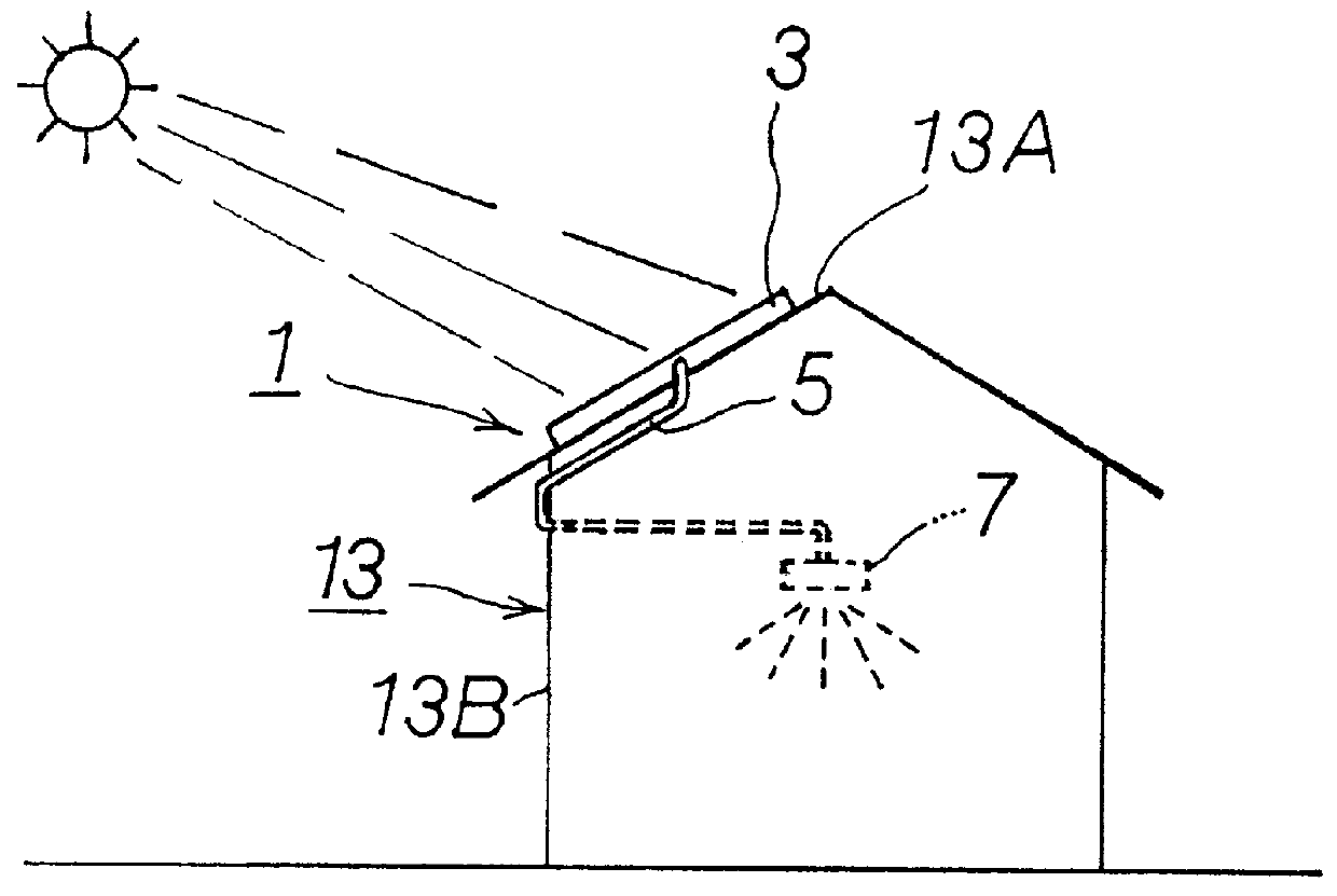
As shown in FIG. 1, the sunlight collection apparatus 1 comprises a light collection section 3 for gathering sunlight, a light conducting section 5 for guiding the sunlight gathered at the light collection section 3, and a light scattering section 7 for shining the sunlight guided by the light conducting section 5 indoors.

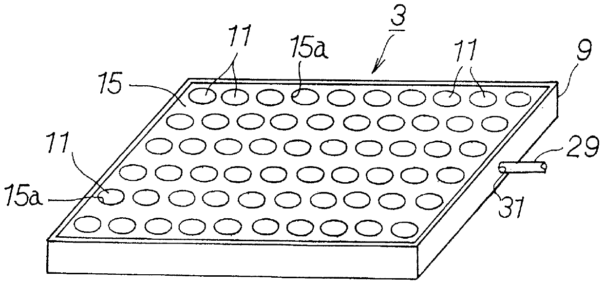
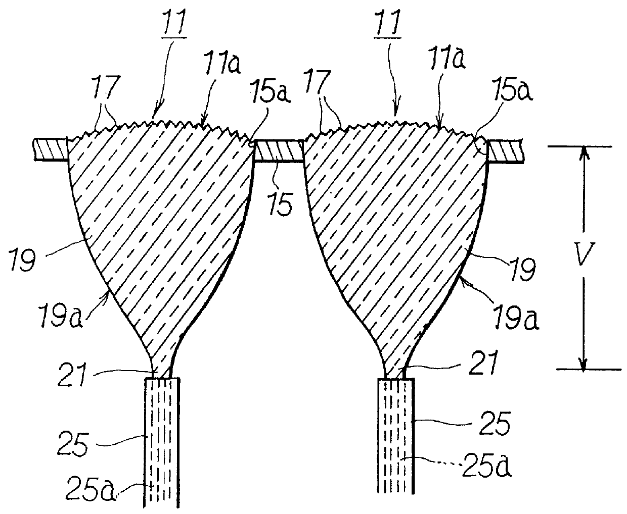
As shown in FIG. 2, the light collection section 3 has a rectangular case 9 having a designated depth. A plurality of lens elements 11 formed into small-diameter circles with the front surfaces 11a (FIG. 3) acing the sun are arranged inside the case 9 toward the upper portion of the case 9, which can, for example, be installed at a designated angle of inclination facing southwards on a rooftop 13A of a building 13. The case 9 is a thin box with an open upper portion, to the top of which a support panel 15 has been affixed as shown in FIG. 3. Support...

second embodiment

the light collection section according to the present invention will be explained with reference to the drawings. FIG. 6 is a perspective view showing a light collection section of the present embodiment, and FIG. 7 is a perspective view showing a lens element. In the present embodiment, the light collection section 3' of the sunlight collection apparatus 1 has a different structure. That is, as shown in FIG. 6, the light collection section 3' of the present embodiment has a plurality of lens elements 11' arranged within a rectangular case 9, each lens element 11' having a planar shape wherein the planar surface of the case 9 facing the sun is divided into a plurality of identical shapes. While the front surface of the case has been divided into rectangles in the present embodiment, the shapes are not restricted thereto, so that the surface may be divided into other shapes, such as polygons, triangles or hexagons, and the shape of the front surface of each lens element 11' can be fo...

third embodiment

the light collection section according to the present invention will be explained with reference to the drawings. FIG. 17 is a front view showing a tree-type light collection section wherein a plurality of light receiving sections are arranged into a tree shape, according to the third embodiment of the light collection section of the present invention. FIG. 18 is a perspective view showing a light collection section. FIG. 19 is a perspective view showing a lens element taken from a portion of the light collection section. According to the present embodiment as shown in FIG. 17, the light collection section 73 of the sunlight collection apparatus 71 has a structure such as to allow installation, not on the roof 13A of a building 13, but in a well-lit location such as a yard. Therefore, it is installed in tree-form wherein a plurality of light collection sections 73 shaped like the leaves of a tree are provided on a pole (support pole) 37. As shown in FIG. 18, each leaf-shaped light c...


PUM


Abstract

The present invention relates to a sunlight collection apparatus with increased sunlight gathering and receiving capabilities, which is cheap to produce and allows reliable collection of sunlight without having to track the sun. This sunlight collection apparatus has a light collection portion, facing toward the sun, for collecting sunlight; a light conducting portion, having optical fiber cables, for conducting sunlight collected by said light collection portion indoors; and a light scattering portion, provided at a tip of said light conducting portion, for lighting a room with sunlight conducted by said light conducting portion. The light collection portion has a plurality of lens elements arranged facing in the direction of the sun, with the front surface of each lens element which faces toward the sun having a curved surface. The lens elements have a tapered shape in a rearward direction from the front surface. A guide portion for guiding sunlight entering into the lens element is built into each lens element. This guide portion is coupled with an optical fiber cable from the light conducting portion.

Description

1. Technical Field of the InventionThe present invention relates to a sunlight collection apparatus for gathering sunlight from outdoors and guiding the sunlight by means of optical fiber cables to shine inside greenhouses for plant cultivation or inside residences.2. Related ArtIn recent years, various types of sunlight collection apparatuses for gathering sunlight, i.e. natural light, and guiding the light to shine inside greenhouses for plant cultivation or inside residences. This type of sunlight collection apparatus usually comprises a light condenser section for gathering sunlight from outdoors to a single area, a light conducting section for guiding the sunlight gathered at the light collection section, and a light scattering section for irregularly reflecting the sunlight guided by the light conducting section indoors. Conventional sunlight collection apparatuses can be largely divided into (1) types which use ducts as the light conducting means and (2) types which use optic...

Claims


Application Information

Patent Timeline
Patent Type & Authority Patents(United States)
IPC IPC(8): F21S11/00G02B6/00G02B7/182H01L31/058H01L31/052
CPCA01G9/243F21S11/00F24J2/067Y02B10/70Y02E10/40Y10S385/90F24S23/12Y02E10/52Y02P60/12Y02A40/25
Inventor YOSHINO, KAZUO
Owner YOSHINO KAZUO
Why Eureka
Try Eureka