Method and apparatus for logging non-circular boreholes

a non-circular borehole and logging method technology, applied in the field of non-circular borehole logging and logging techniques, can solve the problems of poor contact between the pad and the log, and affect the quality of the log

Inactive Publication Date: 2000-05-23
SCHLUMBERGER TECH CORP
View PDF12 Cites 27 Cited by
  • Summary
  • Abstract
  • Description
  • Claims
  • Application Information

AI Technical Summary

Problems solved by technology

Unfortunately, as illustrated on FIG. 1, the "long axis" regions of the borehole wall are rugose as a result of breakout, which results in a poor contact between the pad and the borehole wall, thus severely affecting the quality of the logs.
Such arrangement has led to some improvement over short sections of the borehole, but does not reliably align the sonde with the "short axis": in nearly circular boreholes, proper alignment is not ensured, and in sections with breakout, it was found that the sonde remained aligned with the long axis despite repeated attempts to correct its orientation.

Method used


Image

  • Method and apparatus for logging non-circular boreholes
  • Method and apparatus for logging non-circular boreholes
  • Method and apparatus for logging non-circular boreholes

Examples


Embodiment Construction

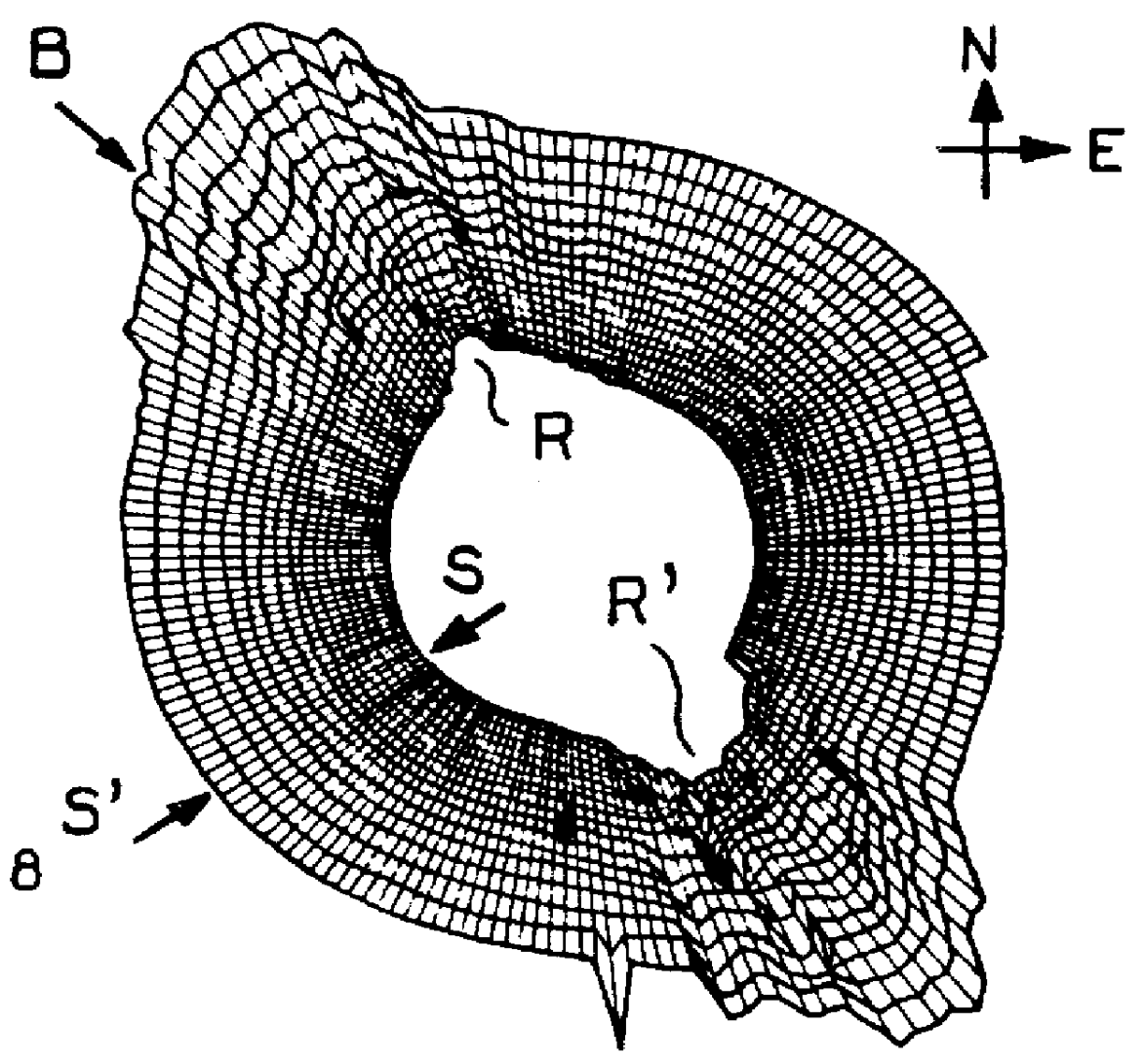
FIG. 1 illustrates the effect of tectonic stress on the geometry of a borehole. The breakout axis is indicated at B. It is apparent on FIG. 1 that while the cross-section of the borehole can be roughly depicted as a "flattened circle", and a "long axis" (substantially aligned with the breakout axis) and a "short axis" can be identified, the cross-section of the borehole is asymmetrical and irregular, and the rugosity of the borehole wall shows wide variations. The borehole wall is extremely rugose in the breakout regions R, R', while it is smooth in the "short axis" region along generatrix S--S'.

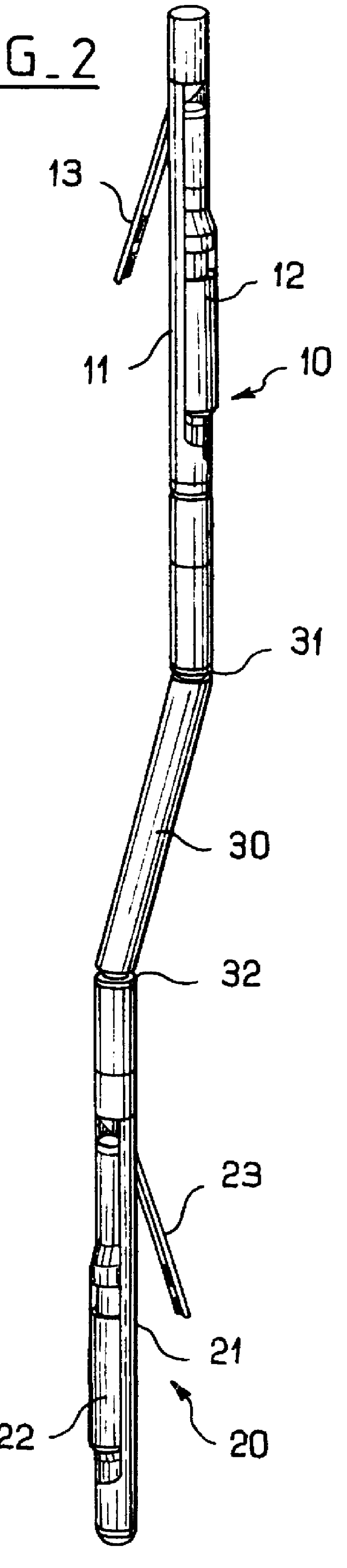
FIG. 2 shows an embodiment of a logging tool string according to the invention. In the described embodiment, the string includes gamma ray density tools, namely Schlumberget's Litho-Density Tool (LDT). But it is to be pointed out that the invention is not limited to a particular type of logging tool and applies to all kinds of logging tools which include a sensor-carrying pad adapted for eng...


PUM


Abstract

The invention relates to a logging method and apparatus adapted for use in non-circular boreholes which, in one embodiment, comprises the use of a first and a second sonde, each sonde having: a pad adapted for contact with the borehole wall, at least a sensor on each pad, and an extendable arm for keeping the pad against the wall of the borehole. The first and second sonde produce measurements related to the same property of the formations, and the first and the second sonde are connected so as to keep the pads aligned with a 90 DEG azimuthal spacing therebetween.

Description

1. Field of the InventionThe invention relates to the logging of subsurface formations traversed by a borehole, by means of logging sondes displaced along the borehole and equipped with a sensor-carrying pad urged into contact with the borehole wall. More specifically, the invention relates to a logging technique adapted for use in stressed boreholes.2. Description of the Prior ArtTectonic stress is known to cause borehole breakout along the direction of least horizontal stress. In that case, the borehole has a larger dimension ("long axis") in the direction of breakout than in the perpendicular direction ("short axis"). A borehole with breakout is exemplified on FIG. 1, which is an ultrasonic image of a 20 centimeters high section of the borehole, shown as if seen from above. This example shows that the shape of the borehole cross-section may be quite irregular, and far indeed from a pure geometrical figure such as an ellipsis or an oval. For that reason, such boreholes shall simpl...

Claims


Application Information

Patent Timeline
Patent Type & Authority Patents(United States)
IPC IPC(8): E21B47/01E21B47/00
CPCE21B47/01E21B47/00E21B49/00
Inventor EDWARDS, JOHN
Owner SCHLUMBERGER TECH CORP
Why Eureka
Try Eureka