Cord winder

a winding device and cord technology, applied in the direction of electric cable installation, thin material handling, cable arrangement between relatively moving parts, etc., can solve the problems of troublesome and time-consuming manual work, the winding device has not provided users with full satisfaction,

Inactive Publication Date: 2000-05-23
MIDORI ELECTRONICS CO LTD A JAPANESE BODY
View PDF7 Cites 51 Cited by
  • Summary
  • Abstract
  • Description
  • Claims
  • Application Information

AI Technical Summary

Problems solved by technology

However, this cord winder has failed to provide users with a full satisfaction because of its inherency originating from a diffi

Method used


Image

  • Cord winder
  • Cord winder
  • Cord winder

Examples


first embodiment

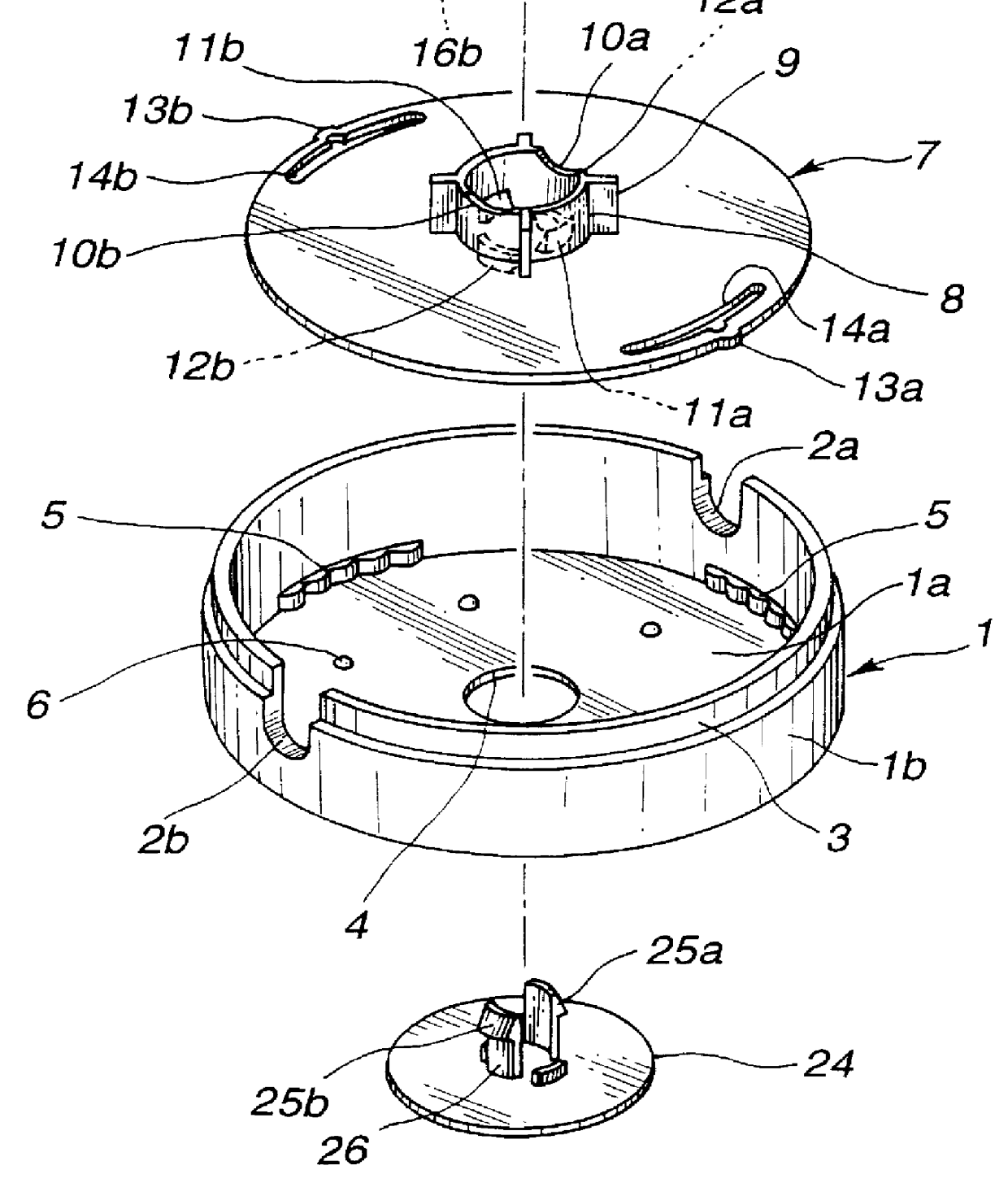
Referring to FIGS. 1 to 7, particularly FIG. 1, there is shown a cord winder 100 which is the present invention.

As is shown in FIG. 1, the cord winder 100 comprises a circular shell 1 including a circular bottom 1a and an annular wall 1b. The annular wall 1b is formed at diametrically opposed portions with rounded cuts 2a and 2b which terminate at a top edge of the annular wall 1b. As shown, a stepped portion 3 is defined around the annular wall 1b near the top edge of the same. A plurality (viz., four in the illustrated embodiment) of check members 5 are provided on the deepest portion of the annular wall 1b at equally spaced intervals. Each check member 5 comprises a plurality of rounded portions lying one after another, as shown. The circular bottom 1a is formed with a circular center opening 4. The circular bottom 1a is further formed around the center opening 4 with a plurality of small semi-spherical projections 6 which are arranged at equally spaced intervals.

Within the circu...

second embodiment

Referring to FIG. 8, there is shown a cord winder 200 which is the present invention.

As will be become apparent as the description proceeds, the cord windier 200 of the second embodiment employs a reduced number of parts as compared with the cord winder 100 of the first embodiment.

That is, the cord winder 200 comprises generally two parts, which are a cylindrical winding cap 30 and a winding disc 39 which are rotatably coupled with each other.

The cylindrical winding cap 30 is formed with a center cylindrical stud 34 which extends downward from a center portion of a circular base portion of the winding cap 30. The center cylindrical stud 34 comprises two stud parts 34a and 34b. The winding cap 30 is further formed in the circular base portion with a cord inserting groove 31 which extends diametrically.

As shown, an annular wall portion of the winding cap 30 is formed at diametrically opposed portions with rounded cuts 32a and 32b which constitute terminal ends of the cord inserting gr...


PUM


Abstract

A cord winder for winding a cord comprises a first structure having a bottomed cylindrical shape and a second structure rotatably held in the first structure. The second structure includes a circular base portion, a center cylindrical stud raised on a center of the circular base portion and radially extending ribs formed on an outer surface of the center cylindrical stud. The ribs are arranged to constitute a bobbin structure. The first and second structures are provided with a cord inserting groove through which the cord can be led to the bobbin structure when the first and second structures take mutually coincident positions. The cord is wound on the bobbin structure when relative rotation takes place between the first and second structures. A braking structure is employed for braking the relative rotation when an external force is applied to the first and second structures to induce the relative rotation. The braking structure includes a curved toothed structure connected to one of the first and second structures and a resilient projection possessed by the other of said first and second structures. The projection is resiliently engaged with the toothed member.

Description

1. Field of the InventionThe present invention relates in general to cord winders, and more particularly to the cord winders of a type which can adjust at need the length of the drawn-out part of the cord.2. Description of the Prior ArtHitherto, various types of cord winders have been proposed and put into practical use particularly in the field of household and office electric apparatuses, such as electric cleansers, electric toasters, personal computers and the like.One of the conventional cord winders is described in Japanese Utility Model Second Provisional Publication 3-8692, which was proposed by the same applicant.The cord winder of this publication generally comprises an upper shell, a lower shell, a hinge structure provided between the upper and lower shells and at least one take-up stud provided by the lower shell. However, this cord winder has failed to provide users with a full satisfaction because of its inherency originating from a difficulty in handling the same. That...

Claims


Application Information

Patent Timeline
IPC IPC(8): H02G11/02H02G11/00B65H75/42B65H75/40
CPCH02G11/02B65H75/42
Inventor MATSUBARA, KAZUO
Owner MIDORI ELECTRONICS CO LTD A JAPANESE BODY
Why Eureka
Try Eureka